

Why Is My Peristaltic Pump Flow Rate Unstable
TROUBLESHOOTING & FAQS
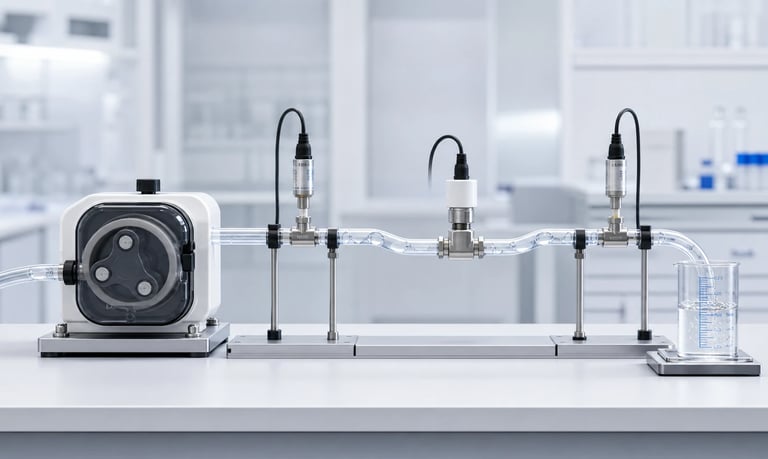
Unstable peristaltic pump flow can result from measurement error, normal cyclic pulsation, tubing wear or installation, incomplete inlet refill, air leaks, bubbles, changing pressure, fluid properties, temperature, motor speed, or an unsuitable calibration method.
Why Is My Peristaltic Pump Flow Rate Unstable?
An unstable peristaltic pump may show fluctuating sensor readings, inconsistent doses, gradual flow drift, intermittent delivery, or a different output after startup. These symptoms do not all have the same cause.
Peristaltic pumps naturally produce cyclic flow as rollers compress and release the tube. A rapidly oscillating instantaneous reading may be normal pulsation, while a changing average over several revolutions can indicate tube wear, incomplete refill, air entry, pressure variation, temperature change, motor-speed instability, or a measurement problem.
A useful diagnosis starts by defining the symptom and changing one condition at a time. Replacing the pump before checking the surrounding fluid path may leave the real cause untouched.
Define What "Unstable" Means
Record the behavior in measurable terms. The time scale often points toward the cause.
Common patterns include:
A repeating fluctuation during every rotor revolution
Different volumes from one short dose to the next
Flow that gradually falls during hours of operation
Flow that rises as the system warms
Random interruptions or bubbles at the outlet
A step change after replacing tubing or opening the pump head
Flow that changes with reservoir level
Flow that becomes nonlinear at higher speed
A stable pump command with an unstable sensor display
Define whether the problem affects instantaneous flow, an average over a set interval, total delivered volume, or individual dose repeatability. Record the averaging time and acceptable variation.
Also note when the symptom begins: immediately after startup, only when cold, after long idle, near the end of a reservoir, at one speed, under pressure, or after a certain number of operating hours.
Verify the Measurement Before Changing the Pump
The measurement system can create or exaggerate apparent instability. Confirm the result with a suitable reference method.
For flow-sensor measurements, review:
Sensor range and resolution
Response time and bandwidth
Sampling rate and digital filtering
Required inlet and outlet conditions
Sensitivity to pulsation, bubbles, viscosity, and temperature
Added pressure loss and internal volume
Installation orientation and trapped-gas points
Calibration fluid and current calibration status
A fast sensor can show real roller pulses that a slow display previously hid. A slow sensor may miss short interruptions. A low sampling rate can alias a high-frequency pulse into a false slow oscillation.
For a reference check, collect liquid over a defined number of complete pump revolutions and measure mass with an appropriate balance. If volume is needed, use verified fluid density at the test temperature. Control evaporation, splashing, and scale vibration.
Short collection periods can produce different results depending on where the test starts and stops within a roller cycle. Use a longer interval or synchronize the measurement when assessing average flow.
Separate Normal Pulsation from Flow Instability
Peristaltic pumps deliver liquid in successive trapped volumes. Roller entry, roller exit, tube recovery, and the transition between rollers create a repeating waveform.
If the pulse shape and average flow remain consistent, the pump may be operating normally even though the instantaneous value oscillates. The application may still require pulsation reduction, but that is different from random instability.
Compare the waveform with rotor speed. Mechanism-related pulsation repeats at a frequency connected to the number of roller events. Irregular peaks, missing pulses, or a changing mean suggest an additional issue.
When testing short doses, include complete and repeatable rotor cycles where practical. A dose containing only part of a cycle can vary with the start position even when long-term average flow is stable.
Inspect the Peristaltic Tubing
The tube is the pumping chamber and a primary wear component. Its dimensions, elasticity, surface condition, and recovery directly affect displaced volume.
Inspect the compressed section for:
Permanent flattening or compression set
Cracks, cuts, abrasion, or thinning
Swelling, softening, hardening, or tackiness
Discoloration or chemical attack
Particle generation
Kinks or twisting
Incorrect tube size or wall thickness
Movement through the pump head
Compare the installed tube with the approved part number and lot. Tubes from the same broad material family can have different dimensions, hardness, formulation, and fatigue behavior.
If flow changes after tube replacement, check installation and allow only the validated run-in or calibration procedure. Do not assume a new tube must reproduce the exact calibration of an aged tube.
Replacing the tube can be a useful diagnostic step, but keep the removed tube and record its operating history. Otherwise, evidence of the cause may be lost.
Check Tube Installation and Pump-Head Closure
Incorrect installation can create immediate or intermittent flow errors. Verify that the tube is centered in the track, free of twist, and routed without side load.
Check:
Pump head fully closed and latched
Correct tube guides or retainers
Tube seated in the intended track
No stretching between inlet and outlet anchors
Correct insertion length and clamp position
No sharp bend at the pump-head ports
Correct rotor and track components
Fasteners and adjustable settings within approved limits
Tube stretch can reduce cross-sectional area or cause the tube to migrate. Excess slack can form a kink or rub against moving parts.
If the head is adjustable, record the actual occlusion setting. An unmarked manual adjustment makes results difficult to reproduce between operators and units.
Verify Occlusion
Occlusion must be sufficient to separate inlet and outlet trapped volumes and limit backflow, but excessive compression is also harmful.
Too little occlusion may cause:
Backflow or slip under outlet pressure
Loss of prime
Reduced or inconsistent displacement
Siphoning when stopped
Too much occlusion may cause:
Higher motor current and heat
Faster tube fatigue
Tube damage or particle generation
Speed variation under load
Reduced service life
Temperature, tube tolerances, wear, chemical exposure, and pump-head geometry can change effective occlusion. Validate the approved setting with new and aged production tubing across pressure and temperature.
Do not increase compression as a universal correction for low flow. Measure current, temperature, flow, leakage, and tube condition before and after any permitted adjustment.
Look for Inlet Air Leaks
The suction side can draw air through a small leak without leaking liquid outward. Intermittent bubbles then reduce delivered liquid volume and create unstable sensor or dose results.
Inspect:
Reservoir pickup and cap
Tube-to-fitting joints
Cracked or hardened tubing
Loose clamps
Threaded fittings and seals
Selector valves and manifolds
Filter housings
Sample ports and unused branches
Air entry may worsen as reservoir level falls because inlet vacuum increases. It may also appear only at high speed, high viscosity, or cold temperature.
Use a leak-test method appropriate to the fluid path and pressure limits. Avoid applying a test pressure or vacuum that can damage the pump tubing, reservoir, sensors, or valves.
Transparent tubing can help locate bubbles, but very small bubbles may merge or appear only after pressure changes. Confirm the leak with measured flow, pressure, or a controlled isolation test.
Eliminate Trapped Bubbles and Poor Priming
Gas is compressible, so bubbles can absorb and release pump displacement. They may cause delayed output, missing liquid pulses, post-stop dripping, and inconsistent short doses.
Bubbles can enter from leaks, an empty pickup, turbulent reservoir return, fluid outgassing, poor filling, or a cleaning process. High points, sensor chambers, filters, and large fittings can trap them.
Review the priming sequence:
Start from the actual dry or partially filled condition
Use a speed that allows complete tube refill
Provide enough time to clear the longest path
Orient components so gas can leave
Avoid drawing a vortex near the reservoir pickup
Confirm that the reservoir is vented
Define a timeout and safe response for failed prime
Fast priming is not always better. High speed can increase inlet vacuum and incomplete refill, particularly with viscous fluid.
After priming, allow a defined stabilization period only if the production process does the same. Otherwise, include the startup transient in the performance requirement.
Reduce Excessive Inlet Resistance
The tube must reopen and fill after each roller passes. If liquid cannot reach the pump quickly enough, displacement per revolution becomes incomplete and may vary.
Inlet resistance increases with:
Higher viscosity
Lower fluid temperature
Longer or smaller-bore tubing
Narrow fittings and valves
Fine or loaded filters
Excessive suction lift
Poor reservoir venting
Kinks or soft-tube collapse
A common sign is a speed-to-flow curve that flattens at higher speed. Increasing motor command then produces little additional flow and may increase instability.
Measure inlet vacuum near the pump under the worst reservoir level, viscosity, temperature, and speed. Shorten and enlarge the inlet path where practical, remove unnecessary restrictions, and use tubing that resists collapse.
Changing only the outlet path will not correct incomplete inlet refill.
Check Outlet Pressure and Restrictions
Peristaltic flow can change with outlet pressure because tubing expands, occlusion permits slip or backflow, fittings and dampers store volume, and the motor may slow under load.
Check for:
Loaded or partially blocked filters
Narrow nozzles
Valves with variable opening pressure
Kinked tubing
Changing elevation
Downstream process-pressure variation
Crystals, particles, or dried residue
A full or pressurized receiving container
Measure steady and peak pressure close to the pump and at the process-critical point where needed. A slow gauge may hide roller-related pressure peaks.
If instability appears only after long operation, inspect components that accumulate material or change with temperature. Cleaning the system may temporarily restore flow, but identify and control the reason for repeated restriction.
Control Fluid Viscosity and Temperature
Many liquids become more viscous when cold. Higher viscosity increases inlet and outlet resistance and can prevent complete tube refill. Temperature also changes tubing flexibility, recovery, dimensions, and pressure behavior.
Record fluid temperature near the pump, not only room temperature. Also measure enclosure, pump-head, and motor temperature during warm-up.
A flow rate that rises gradually may be caused by:
Fluid viscosity falling as it warms
Tubing becoming softer or changing recovery
Motor or driver behavior changing with temperature
Pressure loss changing in the fluid path
Test cold startup and stabilized operation separately. If the process requires calibration over a wide range, use validated temperature-specific compensation or feedback rather than assuming one linear correction.
For non-Newtonian fluids, viscosity can also change with shear, rest time, mixing, or fluid age. Document the preparation and measurement method.
Verify Motor Speed and Drive Stability
Flow cannot remain stable if rotor speed changes unexpectedly. Confirm actual speed rather than relying only on the command value.
Possible causes include:
Supply-voltage variation or droop
Driver current limiting
Motor heating
Gearbox wear or backlash
Excessive tube compression
Changing mechanical or pressure load
Unstable PWM or analog command
Communication errors
Poor connector contact
Control-loop tuning
Record command, speed feedback where available, voltage, current, pressure, and flow on a common time base. Correlation helps distinguish electrical, mechanical, and fluid causes.
PWM frequency and duty range should match the motor and driver design. Very low commands may produce irregular rotation or stall on some configurations.
If closed-loop speed control is used, verify sensor resolution and tuning across load. A stable average motor speed does not necessarily eliminate cyclic speed ripple under roller compression.
Review Reservoir and Fluid Handling
Changes upstream of the pump can alter delivery even when the pump is healthy.
Check:
Reservoir vent open and adequately sized
Pickup remains submerged
No vortex formation
Fluid does not separate or settle
Agitation is consistent
Concentration does not change through evaporation
Return flow does not entrain air near the pickup
Flexible reservoir does not collapse incorrectly
Source pressure remains within the intended range
Suspensions may settle during idle and change viscosity or solids concentration. Foaming fluids may feed a mixture of gas and liquid. Sticky products may form a skin or deposit around the pickup.
Test full and near-empty reservoir states, after the longest idle period, and with the production filling and agitation sequence.
Check Calibration and Control Logic
A calibration factor derived from one condition may not remain valid after tubing wear, pressure change, fluid replacement, or temperature shift.
Review:
Units and conversion factors
Mass-to-volume density value
Calibration fluid and temperature
Pump speed and pressure during calibration
New or aged tube condition
Command timing and acceleration
First-dose handling
Stored coefficient limits and integrity
Recalibration trigger and procedure
Avoid recalibrating immediately whenever flow appears unstable. Calibration can hide a changing mechanical or fluid problem without making it stable.
First establish that repeated measurements under fixed conditions are consistent. Then calibrate the controlled operating state.
If the system uses flow, weight, or level feedback, inspect sensor filtering and controller tuning. An aggressive loop can chase natural pulsation and create speed oscillation.
Consider Tubing Run-In and Long-Term Drift
Peristaltic tubing can change during early operation and throughout service. Stress relaxation, compression set, surface wear, chemical exposure, and heat may alter flow.
Define whether a controlled run-in is required before final calibration. The procedure should specify fluid, speed, pressure, duration, and temperature. Do not use an informal operator-dependent waiting period.
During life testing, measure flow at consistent reference conditions. Track:
Average flow and dose repeatability
Tube dimensions and visible condition
Motor current and pump-head temperature
Inlet vacuum and outlet pressure
Leakage or backflow
Prime time
Use multiple tubes and pump samples to understand variation. Replacement intervals should be based on representative testing and application limits rather than a universal tubing-life claim.
Use a Structured Isolation Test
Change one part of the system at a time while keeping a baseline configuration.
A practical sequence is:
Confirm the symptom with a reference measurement.
Record the waveform, average flow, speed, pressure, temperature, and bubbles.
Test a short, low-resistance inlet from a controlled reservoir.
Test a short, low-resistance outlet into an open receiver.
Install verified new tubing using the approved procedure.
Restore production inlet components one at a time.
Restore production outlet components one at a time.
Repeat at the temperature, viscosity, and pressure where the fault occurs.
This sequence helps distinguish pump-head or tube behavior from the surrounding system. Observe pressure limits and containment requirements when changing the setup.
Do not discard a failed component until its identity, orientation, condition, and operating history are documented.
Unstable-Flow Troubleshooting Checklist
Define whether the issue is pulsation, dose variation, drift, or interruption
Record the time scale and operating condition where it appears
Confirm the result with an appropriate reference measurement
Check sensor range, bandwidth, sampling, filtering, and orientation
Compare the waveform with rotor position or speed
Inspect tube part number, lot, wear, chemistry, and dimensions
Verify tube seating, tension, head closure, and approved occlusion
Check inlet joints for air entry
Remove trapped bubbles and validate the prime sequence
Measure inlet vacuum at worst reservoir level and viscosity
Measure outlet pressure and transient peaks
Inspect filters, valves, nozzles, and tubing for restriction
Record fluid, pump-head, enclosure, and motor temperature
Confirm viscosity and non-Newtonian behavior where relevant
Measure actual rotor speed, voltage, current, and command stability
Check reservoir venting, pickup, agitation, and fluid separation
Review calibration conditions, coefficients, and control-loop tuning
Compare new, run-in, and representative aged tubing
Reproduce the fault with the final fluid path and enclosure
Document changes and replace only one variable at a time
Common Troubleshooting Mistakes
Treating normal roller pulsation as random instability
Measuring for less than a complete pump cycle
Trusting one sensor without checking its bandwidth or restriction
Replacing the pump before inspecting the inlet path
Looking for liquid leaks but not suction-side air entry
Increasing speed when the tube cannot refill
Increasing occlusion without checking load and tube life
Calibrating over a drifting fault
Testing only with water instead of the production fluid
Measuring room temperature instead of fluid and pump-head temperature
Ignoring reservoir level and venting
Changing several parts at once and losing the root cause
Comparing a new tube directly with an aged calibration
Filtering the display until the instability is hidden
Frequently Asked Questions
Why does my peristaltic pump flow fluctuate on the sensor?
The sensor may be detecting normal roller pulsation, bubbles, speed variation, pressure changes, or a measurement artifact. Compare the signal with rotor speed and confirm average flow independently.
Why does flow decrease after the pump runs for a long time?
Tubing wear, compression set, rising temperature, changing pressure, filter loading, fluid changes, or motor behavior may contribute. Record flow, current, pressure, and temperature throughout the run.
Why is peristaltic pump flow unstable at high speed?
The tube may not refill completely because viscosity or inlet resistance limits fluid entry between roller passes. Motor-speed or pressure effects can also become more significant.
Can air leaks occur without liquid leaking out?
Yes. A suction-side connection can draw air inward under vacuum while showing no outward liquid leak. This often creates bubbles and intermittent delivery.
Should I recalibrate when the flow becomes unstable?
First identify and correct the source of variation. Calibration changes the average relationship between command and output but does not fix an unstable mechanical, fluidic, or measurement condition.
When should peristaltic pump tubing be replaced?
Use a replacement interval validated for the exact tube, pump head, speed, pressure, fluid, temperature, and duty cycle. Replace earlier if inspection or performance reaches the defined service limit.
Kamoer Peristaltic Flow Troubleshooting Support
Kamoer can help evaluate pump-head geometry, tubing, occlusion, inlet refill, pressure, fluid properties, motor control, calibration, measurement methods, and representative testing for unstable peristaltic pump flow.
Related Stories
Kamoer Fluid Tech (Shanghai) Co., Ltd.
pump@kamoer.com