

Why Is My Micro Pump Overheating
TROUBLESHOOTING & FAQS
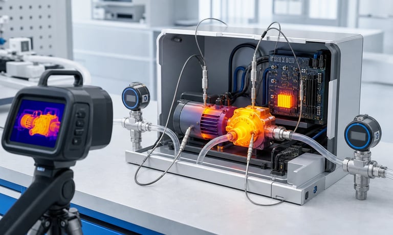
A micro pump can overheat when hydraulic or pneumatic load raises motor torque, the inlet or outlet is restricted, peristaltic tube compression is excessive, fluid viscosity is high, voltage or driver settings are unsuitable, the pump stalls or runs too long, or the final enclosure cannot remove heat.
Why Is My Micro Pump Overheating?
A micro pump produces heat in its motor, driver, gearbox, bearings, pumping mechanism, and fluid path. Some temperature rise is normal. Overheating becomes a problem when temperature continues rising, protection activates, flow changes, materials age faster, the fluid is affected, or measured temperatures exceed the approved limits for the exact pump and system.
The pump may not be the original heat source. Excessive outlet pressure, a restricted inlet, viscous fluid, tight peristaltic occlusion, incorrect voltage, unstable control, repeated stalls, nearby electronics, and a sealed enclosure can all raise temperature.
Troubleshooting should connect temperature with time, current, speed, flow, inlet vacuum, outlet pressure, voltage, and operating mode. Replacing the pump without measuring its load may reproduce the same failure.
Define What Is Overheating
Do not diagnose overheating by touch alone. Surface temperature, internal winding temperature, driver junction temperature, fluid temperature, and allowable user-contact temperature are different quantities.
Record the symptom:
Motor or pump head feels unusually hot
Flow decreases after warm-up
Driver or motor protection activates
Pump restarts after cooling
Current rises over time
Tube, valve, seal, or fluid changes with heat
Enclosure temperature exceeds the design target
Odor, discoloration, noise, or mechanical drag appears
Temperature continues rising instead of stabilizing
Identify the limit being evaluated and its source. A supplier component limit, an OEM reliability target, a material limit, and a product safety requirement may not be the same.
Measure temperature at defined locations with a controlled method. A single external reading cannot prove the temperature of hidden windings or electronic components.
Record Temperature over Time
Thermal behavior is a curve, not one number. Begin logging before startup and continue until the system reaches a defined steady condition or an approved stop limit.
Record together:
Ambient and enclosure-air temperature
Motor, driver, gearbox, pump-head, and critical tube temperature
Fluid inlet and outlet temperature
Supply voltage at the pump
Current and input power
Pump command and actual speed
Inlet vacuum and outlet pressure
Flow or dose
Fan or cooling state
Note startup, priming, speed changes, valve events, blockage, idle, and shutdown. These timestamps help connect temperature changes with load.
If temperature is still rising at the end of a short test, the result does not represent steady operation. Continue only within approved safety and component limits.
For intermittent systems, log several complete cycles. Thermal accumulation can occur even when each individual run is brief.
Verify the Temperature Measurement
Thermocouples, resistance sensors, infrared cameras, and internal electronic sensors each have limitations.
Check:
Sensor type, range, accuracy, and calibration status
Attachment method and contact pressure
Exact measurement location
Thermal paste, tape, or adhesive influence
Sampling interval
Infrared emissivity and reflected surfaces
Airflow around the sensor
Difference between case and internal temperature
An infrared reading from shiny metal can be misleading if emissivity is not controlled. A large taped sensor can change local cooling. An internal driver reading may be filtered or represent a different point than the pump case.
Use repeatable locations and photographs. Compare similar surfaces using the same method.
When a hidden internal limit matters, use supplier guidance, embedded sensing, electrical estimation, or a validated correlation rather than assuming external case temperature equals the internal value.
Establish a Low-Load Baseline
Test the pump in a controlled, low-resistance configuration within its approved operating conditions.
For a liquid pump, use:
Short, adequately sized inlet tubing
Nearby vented reservoir
Suitable test fluid at controlled temperature
Short outlet into an open receiver
For a gas pump, use short, low-restriction inlet and outlet paths with the correct gas and flow measurement basis.
Record temperature, current, speed, and flow. If the pump overheats in this reference setup, investigate voltage, driver, motor, gearbox, pump head, internal valves, bearings, assembly, and sample condition.
If temperature returns to normal, restore production inlet and outlet components one at a time. This identifies which restriction, pressure, routing, or control state adds load.
Do not run outside supplier limits merely to establish a baseline.
Check Outlet Pressure and Blockage
Higher outlet pressure usually requires more motor torque or changes internal leakage and valve behavior. Current and heat may rise as the pump works harder.
Inspect:
Kinked or crushed tubing
Narrow fittings
Closed or partially opening valves
Loaded filters
Small nozzles
Crystals, particles, or dried residue
Excessive elevation
Pressurized receiving containers
Incorrectly installed check valves
Measure outlet pressure close to the pump. Capture startup and valve-switching peaks; a slow gauge may show only a lower average.
A pump may appear to deliver acceptable flow while operating near an excessive load. Flexible tubing and dampers can store pressure and hide short peaks.
Test normal, maximum expected, and controlled blocked conditions only when approved. Define a timeout, current limit, pressure limit, and safe shutdown for foreseeable blockage.
Check Inlet Restriction
Inlet restriction can also increase load and reduce cooling or pumping efficiency. The pump may run longer to deliver the same amount while chamber or tube refill becomes incomplete.
Common causes include:
Long, small-bore inlet tubing
Loaded filters
Narrow fittings and valves
Excessive suction lift
Poor reservoir venting
High viscosity
Cold fluid
Collapsed flexible tubing
Blocked pickup
Measure inlet vacuum at the pump under the lowest reservoir level and worst fluid condition. Check tube shape and reservoir behavior.
For a peristaltic pump, incomplete refill can flatten the speed-to-flow curve. Increasing speed then adds mechanical cycles and heat without proportional flow.
For a diaphragm pump, high inlet restriction can reduce chamber filling and alter valve dynamics while the motor continues working.
Reduce unnecessary restriction and correct venting rather than compensating with longer run time or higher speed.
Evaluate Fluid Viscosity and Temperature
Viscous liquid raises inlet and outlet resistance and may require more torque. Many fluids become much more viscous when cold, so the highest load may occur at startup.
Record:
Fluid identity and lot
Viscosity with temperature and measurement method
Coldest startup condition
Normal stabilized condition
Non-Newtonian or yield-stress behavior
Particles, crystals, or curing behavior
Heating during operation may reduce viscosity and motor load, but it can also change tubing, valves, seals, chemical compatibility, evaporation, and product stability.
Do not heat a fluid merely to solve pump temperature without reviewing the process and safety consequences.
Test the exact fluid or a justified representative. Water may produce normal temperatures while the production liquid overloads the pump.
For fluids that thicken, settle, crystallize, or cure during idle, reproduce the longest expected restart interval.
Check Peristaltic Tube Occlusion
Peristaltic pumps require enough tube compression to separate inlet and outlet volumes. Excessive occlusion increases roller force, motor torque, current, tube heating, and wear.
Check:
Correct tube part number and dimensions
Tube material and hardness
Pump-head closure and latch
Adjustable occlusion setting
Tube seating, twist, and tension
Temperature and chemical swelling
New and aged tube behavior
Roller and track condition
A tube that physically fits may still be too large, thick, or stiff for the head.
Do not loosen occlusion until temperature falls without checking leakage, backflow, pressure, flow, and approved settings. Too little compression can create another failure.
Measure motor current and pump-head temperature with production tube tolerances at minimum and maximum temperature. Include chemically exposed and representative aged tubing.
Inspect Mechanical Drag
Bearings, gears, rollers, eccentric drives, couplings, and diaphragms can create excessive friction or load.
Look for:
Rough or tight rotation
Gear damage or inadequate lubrication
Misaligned shaft or coupling
Roller bearing wear
Foreign material in the pump head
Housing distortion from mounting
Loose parts rubbing
Diaphragm or linkage interference
Valve damage causing abnormal pressure
Compare current and sound with a verified sample under the same low-load condition. A mechanical problem may produce higher no-load current, irregular speed, or a new frequency component.
Do not rotate, lubricate, or disassemble a pump unless the supplier permits the procedure. Unapproved lubricant can contaminate fluid paths, damage materials, or hide failure evidence.
Retain failed parts and record sample history for root-cause analysis.
Verify Supply Voltage
Incorrect supply voltage can overheat a motor or driver. Undervoltage can also create problems if the controller increases current, the motor stalls, or the pump runs longer to complete the task.
Measure voltage at the pump during:
Startup
Normal load
Maximum pressure or vacuum
Valve switching
Other equipment activity
Minimum and maximum input supply
Check wiring length, conductor size, connector resistance, polarity, power-supply current limit, and voltage ripple.
Do not assume the power-supply setting equals the voltage at the motor. Cable and switching losses can be significant in small low-voltage systems.
Use only the approved voltage range for the exact motor and integrated electronics. A motor nominal voltage does not automatically define the permitted pump-system voltage or PWM method.
Verify Driver and PWM Settings
Driver configuration affects motor current, torque ripple, switching loss, speed stability, and heat.
Review:
PWM frequency and duty range
Stepper current and microstep mode
Brushless commutation and current limit
Acceleration and deceleration
Closed-loop gains
Holding current
Braking and reversal
Stall detection and retry
Switching-device temperature
A stepper motor can draw substantial current while holding or running slowly. Reducing idle current may lower heat but also reduce holding torque.
Changing PWM frequency may affect motor torque, acoustic noise, driver loss, electromagnetic compatibility, and temperature. Use settings approved for the motor and driver.
An unstable speed loop may command repeated acceleration in response to cyclic peristaltic or diaphragm load. Log command, actual speed, current, and pressure together.
Check Motor Type and Wear
Brushed and brushless motors have different heat and failure mechanisms.
Brushed motors can develop increased resistance, arcing, unstable contact, or friction as brushes and commutator surfaces change. Brushless systems remove brush wear but add electronic commutation, sensors, and driver losses.
Both types still depend on:
Bearings
Windings and insulation
Magnets
Gearbox
Connectors
Pump mechanism
Thermal path
Compare current, speed, temperature, and noise across new and aged samples. A motor that slows under load may draw more current or extend pump run time.
Do not assume a brushless pump cannot overheat or that a brushed pump is unsuitable. Match the complete motor-driver-pump system to the load and duty cycle.
Review Duty Cycle and Run Time
A pump approved for short intermittent operation may overheat if used continuously. A continuous-duty pump may still overheat at excessive pressure, speed, voltage, or ambient temperature.
Record the full cycle:
Run time
Idle time
Starts per period
Prime and purge duration
Normal and peak speed
Pressure and vacuum during each phase
Reversal or braking
Time available to cool
Average duty percentage alone can hide high-current startup, repeated stalls, long prime attempts, or short idle periods that do not allow cooling.
Test the longest continuous run and the most demanding repeated cycle separately.
If software limits duty, verify timing through power cycles, communication faults, clock errors, and reset. A protection counter that clears unexpectedly may allow excessive operation.
Check for Stall and Repeated Retry
A locked rotor or blocked mechanism can produce high current and rapid heating. Some drivers limit current; others cycle through protection or repeatedly attempt restart.
Investigate:
Blocked inlet or outlet
Jammed roller or gear
Excessive tube compression
Cured or crystallized fluid
Sticky diaphragm valve
Cold high-viscosity startup
Mechanical misassembly
Driver commutation failure
Record the fault current, detection time, temperature, retry behavior, and delivered fluid during recovery.
Unlimited retries can accumulate heat and create an unexpected dose after the obstruction clears. Define a maximum attempt count, cooldown, user indication, and safe recovery.
Current thresholds must account for normal cold startup and production variation. A threshold that is too low creates false faults; one that is too high may not protect the system.
Evaluate the Final Enclosure
An open-bench pump can run much cooler than the same pump inside a compact product.
Review:
Enclosure volume
Vent openings
Natural or forced airflow
Pump orientation
Proximity to power supplies, processors, heaters, and batteries
Insulation and acoustic foam
Cable and tube obstruction of airflow
Dust filters and loading
Product mounting and external surface
Heat from adjacent components can raise the pump's starting temperature before it runs. The pump can also warm the fluid and nearby tubing.
Measure temperature in the closed production enclosure at minimum and maximum ambient conditions. Include realistic dust, filter, fan, and vent states.
Repeat thermal tests after adding noise insulation, seals, protective covers, or packaging changes. Small enclosure modifications can alter airflow significantly.
Improve Cooling without Creating New Problems
Cooling options may include:
Moving the pump away from heat sources
Improving conductive contact to a suitable chassis
Adding controlled ventilation
Increasing spacing around the motor and driver
Reducing unnecessary power loss
Selecting a more efficient operating point
Reducing pressure or fluid-path resistance
Using a pump with more suitable torque margin
Do not attach a heat sink or metal bracket without checking vibration transmission, electrical isolation, condensation, fluid leakage, and assembly tolerances.
A fan adds noise, power, dust, and a new failure mode. Natural ventilation may conflict with ingress or contamination requirements.
Thermal design should remove heat from the source and preserve fluid, materials, acoustics, safety, and reliability. Validate the complete product, not only the pump case.
Check Ambient Temperature and Altitude
High ambient temperature reduces the temperature margin between components and surroundings. Altitude lowers air density and can reduce convective cooling.
Test:
Minimum and maximum operating ambient
Storage recovery and cold startup
Enclosure temperature before pump start
Maximum installation altitude or atmospheric-pressure range
Fan or natural-airflow performance
Heat from other product modes
At altitude, gas-pump flow and pressure references also change. A controller may increase speed to maintain standardized flow, adding heat.
Do not apply a universal temperature or altitude derating factor unless it is defined for the exact pump and operating measure.
Use the relevant product safety and compliance process for electrical spacing, insulation, user contact, and environmental limits.
Review Fluid Compatibility and Swelling
Chemical exposure can swell, soften, or harden peristaltic tubing, diaphragms, valves, seals, and bearings exposed by a leak. This can increase friction, occlusion, valve resistance, or mechanical load.
Cleaning agents and mixed waste may be more aggressive than the production fluid.
Inspect for:
Swelling or dimension change
Hardening or softening
Tackiness
Cracking
Valve sticking
Tube flattening
Seal drag or leakage
Deposits and residue
Static compatibility data may not predict dynamic pump load. Test exact finished components under fluid, temperature, pressure, speed, duty, cleaning, and idle conditions.
A temperature rise may accelerate chemical interaction, creating a feedback loop of swelling, higher load, and more heat.
Separate Pump Heat from Process Heat
The fluid or surrounding equipment may heat the pump even when motor losses are normal.
Possible external sources include:
Heated process liquid
Cleaning or sanitizing cycles
Nearby heater
Battery or power supply
Processor or lighting
Warm incoming gas
Hot enclosure wall
Measure temperature before the pump starts and compare powered and unpowered soak tests. Track fluid inlet and outlet temperature.
If hot fluid contacts a peristaltic tube or diaphragm, review material strength, flexibility, chemical compatibility, pressure, and life at that temperature.
Do not attribute every high case reading to electrical overload. Separating external and internally generated heat changes the corrective action.
Use a Structured Isolation Test
A practical sequence is:
Confirm temperature with a controlled measurement.
Log temperature, current, voltage, speed, flow, inlet vacuum, and outlet pressure.
Test the pump with a short low-resistance fluid path.
Verify voltage and driver settings.
Install a verified pump tube or inspect diaphragm and valves as permitted.
Restore inlet components one at a time.
Restore outlet components one at a time.
Repeat the real duty cycle in the final enclosure.
Test ambient, fluid temperature, voltage, and pressure extremes.
Compare multiple pump and consumable samples.
Change one variable at a time and retain the baseline. Avoid adding a fan, changing the tube, lowering speed, and opening the outlet simultaneously because the root cause becomes unclear.
Stop testing if temperature, pressure, current, fluid, or material conditions exceed approved limits.
Overheating Troubleshooting Checklist
Overheating limit and measurement location defined
Temperature logged from startup through steady state
Current, voltage, speed, flow, vacuum, and pressure logged together
Sensor range, attachment, emissivity, and calibration checked
Low-resistance reference test completed
Outlet restriction and pressure peaks measured
Inlet vacuum, reservoir venting, and filter loading checked
Fluid viscosity and cold-start behavior verified
Peristaltic tube size, installation, and occlusion checked
Diaphragm valves, gears, rollers, bearings, and linkage inspected
Voltage measured at the pump under load
PWM, current limit, commutation, and stepper settings reviewed
Stall detection, retry, and recovery tested
Continuous and repeated intermittent duty validated
Final enclosure airflow and nearby heat sources included
Maximum ambient and altitude conditions evaluated
Fluid and cleaning compatibility reviewed for swelling or deposits
Pump-generated heat separated from hot process conditions
Multiple production-representative samples compared
Common Overheating Mistakes
Judging temperature only by touch
Measuring one point before thermal stabilization
Logging temperature without current and pressure
Testing only on an open bench
Blaming the motor before checking a blocked filter or nozzle
Increasing speed to recover flow from incomplete inlet refill
Loosening tube occlusion without checking leakage and backflow
Using water instead of a viscous production fluid
Measuring supply voltage only at the power source
Changing PWM or current without checking driver limits
Ignoring repeated stall retries
Describing intermittent duty only as an average percentage
Adding acoustic insulation without repeating thermal tests
Treating brushless as immune to overheating
Frequently Asked Questions
Is it normal for a micro pump to feel warm?
Some temperature rise is normal, but acceptability depends on the exact pump, operating load, measurement location, enclosure, fluid, duty cycle, and approved component and product limits.
Why does pump temperature rise with back pressure?
Higher pressure generally requires more torque or increases internal losses. Motor current, driver loss, mechanical stress, and heat can rise while flow falls.
Can high viscosity make a micro pump overheat?
Yes. Viscous fluid increases inlet and outlet resistance, startup torque, and run time. Test the maximum viscosity at the coldest operating condition.
Why does a peristaltic pump run hot after replacing the tube?
The new tube may have different dimensions, hardness, installation tension, or occlusion. Confirm the exact approved tube and pump-head setup.
Can undervoltage cause overheating?
It can contribute if the motor stalls, the driver increases current, or the pump runs longer. Measure voltage, current, speed, load, and driver behavior at the pump.
Should I add a fan to cool the pump?
Only after identifying the heat source. A fan may help enclosure cooling but adds noise, dust, power, maintenance, and another failure mode. Validate the complete design.
Kamoer Thermal Troubleshooting Support
Kamoer can help evaluate pump load, pressure, inlet conditions, tubing or diaphragm behavior, motor and driver settings, duty cycle, fluid properties, enclosure temperature, and representative thermal tests for OEM systems.
Related Stories
Kamoer Fluid Tech (Shanghai) Co., Ltd.
pump@kamoer.com