

Why Does Pump Flow Change as the Reservoir Level Drops
TROUBLESHOOTING & FAQS
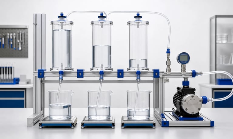
As a source reservoir empties, static inlet pressure and liquid-column geometry change; flow may shift when the pump must create more vacuum, the vent or pickup restricts supply, air enters, bubbles form, a flexible container collapses poorly, or a gravity-assisted and siphoning condition disappears.
Why Does Pump Flow Change as the Reservoir Level Drops?
A positive-displacement micro pump may be expected to deliver the same volume per revolution regardless of reservoir level. In practice, the inlet pressure and fluid path change as the source empties. The pump may need more vacuum to lift liquid, a vent may become restrictive, the pickup may draw a vortex or bubbles, and flexible tubing or a bag may collapse differently.
The effect can appear as gradual flow drift, unstable short doses, longer priming, intermittent bubbles, or a sudden loss of delivery near empty. A reservoir located above the pump can also provide gravity assistance or create a siphon that decreases as liquid level falls.
To diagnose the change, measure source level, inlet pressure at the pump, flow or dose, bubbles, temperature, and motor speed together. Reservoir level is often a system-load variable rather than a pump fault.
Define the Level-Related Symptom
Record the relationship between fluid level and performance.
Possible patterns include:
Flow gradually decreases as the reservoir empties
Dose variation increases only near low level
Bubbles appear below a particular level
Flow rises when the reservoir is placed above the pump
Flow stops suddenly even though liquid remains
The pump loses prime after shutdown at low level
A flexible bag works at first and then stops collapsing
Flow depends on equipment tilt or reservoir orientation
The first dose after refill differs from steady operation
Measure actual liquid-surface height relative to the pump inlet, not only a percentage displayed by a level sensor.
Also record receiving-container level. A rising outlet level or pressure can change pump load at the same time the source level falls.
Distinguish average flow drift from natural pump pulsation. Use a collection interval long enough to include complete pump cycles.
Understand Static Inlet Head
The liquid surface creates a pressure at the pump inlet based on vertical height, fluid density, and system geometry.
When the source surface is above the pump, gravity provides positive inlet head. When it is below the pump, the pump must create vacuum to lift the liquid.
The hydrostatic relationship is approximately:
Static pressure difference = fluid density × gravitational acceleration × vertical height difference
This equation describes the stationary liquid column. During flow, tubing, fittings, valves, filters, and viscosity add pressure loss.
As the reservoir empties, the vertical height difference changes. A tall narrow tank can produce a larger head change than a shallow wide tank with the same volume.
Use minimum and maximum liquid surfaces on the fluid-path drawing. Reservoir shape and installation position matter more than nominal capacity alone.
Positive Inlet Head Can Increase Flow
A reservoir above the pump can help fill a peristaltic tube or diaphragm chamber. The pump may deliver more complete displacement at a given speed, particularly with viscous liquid or a restricted inlet.
As the level falls, this assistance decreases. Flow may then decline if the pump approaches its refill limit.
Positive head can also expose other effects:
Leakage through a stopped pump
Siphoning toward a lower outlet
Increased pressure at inlet fittings
Flooded pump conditions
More liquid released after a tube or diaphragm failure
Do not increase reservoir height solely to improve flow without reviewing shutoff, leakage, pressure, and containment.
Test the full liquid-level range with the pump running and stopped. A design that relies on gravity assistance needs controlled reservoir placement and refill limits.
Suction Lift Increases as Level Falls
If the reservoir surface is below the pump, the required suction lift increases as liquid level drops. The pump must create a lower inlet pressure to raise liquid and overcome inlet losses.
Increasing lift can cause:
Lower chamber or tube filling
Longer priming
More sensitivity to inlet leaks
Tube collapse
Dissolved gas release
Vapor formation with volatile or warm fluid
Reduced flow at high speed
Measure inlet vacuum close to the pump at full, mid, and low reservoir levels. If vacuum becomes more negative while flow falls, the inlet side is likely limiting performance.
Shorten the inlet, increase internal diameter, reduce unnecessary restrictions, lower the pump, or redesign the reservoir where practical.
Do not compare vertical lift with total tube length. Both matter, but they affect the system in different ways.
Reservoir Venting Can Become the Real Limit
A rigid reservoir must admit air as liquid leaves. If its vent is blocked, undersized, wet, or contaminated, internal pressure falls during pumping.
Symptoms include:
Flow gradually decreases with time or volume removed
The container deforms
Flow recovers after opening the cap
Inlet vacuum rises unexpectedly
Bubbles enter through a weak seal
The pump restarts after an idle period as pressure equalizes
Check vent filters, membranes, caps, tubing, valves, and orientation. A hydrophobic vent can become wetted by splash or condensation. Dust and product vapor can load it over time.
Measure reservoir internal pressure where safe and practical. Opening the cap can be a useful diagnostic step only when compatible with fluid safety, cleanliness, and process requirements.
Size the vent for peak removal rate, not only average flow.
Flexible Bags and Collapsible Reservoirs Behave Differently
A sealed flexible bag can supply liquid without admitting air, but it must collapse predictably.
Potential problems include:
Film layers stick together
The bag folds across the outlet
External enclosure features pinch the bag
The outlet port rotates or kinks
Residual gas expands
The bag is overfilled
Vacuum exceeds the bag's collapse behavior
Flow may remain stable until one fold blocks the outlet, creating a sudden failure rather than gradual drift.
Test the full dispense volume in every product orientation. Include transport, vibration, cold film stiffness, hot film softening, and repeated installation.
Use a tray, support, outlet geometry, or evacuation process that promotes controlled collapse. Do not assume a flexible container automatically removes all inlet-pressure variation.
Watch for Vortexing and Air Entrainment
At low level, liquid velocity near the pickup can form a vortex that draws air. Return flow, agitation, narrow reservoirs, and high pump flow increase the risk.
Bubbles may appear intermittently before the pickup is fully exposed.
Reduce risk by reviewing:
Pickup submergence
Distance from walls and bottom
Reservoir cross-sectional area
Pump speed
Return-flow location and direction
Agitation speed
Baffles or anti-vortex features
Fluid viscosity and surface tension
Avoid placing the pickup where it seals against the container bottom or draws settled solids.
Test at the minimum usable level and worst product orientation. A transparent development reservoir can reveal the mechanism, but validate the final opaque or flexible production container separately.
Check Pickup Geometry and Residual Volume
The pump may stop delivering while measurable liquid remains because the pickup cannot access it.
Causes include:
Pickup opening above the lowest point
Tube curling upward
Container tilt
Internal ribs or pockets
Bag folds
Surface tension retaining liquid
Sediment blocking the opening
A filter no longer submerged
Define usable volume separately from total filled volume. The level sensor and software empty threshold should reflect actual pickup performance.
Test slow and fast withdrawal, all approved orientations, and the final mounting tolerance.
If residual product matters, weigh or measure the container after the pump reaches the defined empty state. Do not rely only on drawing volume.
Increasing pickup proximity to the bottom may reduce residual volume but increase blockage by sediment or sealing against the surface.
Inlet Air Leaks Become More Visible at Low Level
As suction lift and inlet vacuum increase, a marginal connection may begin drawing air.
Inspect:
Tube-to-fitting joints
Reservoir cap and pickup seals
Filter housings
Selector valves
Threaded fittings
Cracked or hardened tubing
Unused manifold branches
Pump-port adapters
The joint may remain dry because air enters inward rather than liquid leaking out.
Compare bubble rate and inlet vacuum at full and low level. Temporarily use a short verified inlet from a nearby container to isolate the production path.
Leak testing should reproduce the vacuum direction and magnitude. A positive-pressure test may not reveal the same interface behavior.
Correct the joint design and assembly control rather than calibrating around a variable air fraction.
Peristaltic Tube Refill Can Change
After a roller passes, the tube must reopen and draw liquid from the reservoir. Lower inlet pressure, higher viscosity, high speed, and restricted tubing reduce refill.
Signs of incomplete refill include:
Speed-to-flow curve flattening
Reduced flow at low reservoir level
Tube remaining partially flattened
Higher inlet vacuum
Greater dose variation
Bubbles or delayed prime
Lower speed may allow more refill time, but it also changes dispense time and pulsation frequency.
Use adequate inlet bore, short routing, suitable tube recovery, and a pump speed validated at minimum level.
Do not increase occlusion to correct low-level flow. Excess compression increases motor load and tube wear and does not remove inlet restriction.
Test new and aged tubing because recovery changes during service.
Diaphragm Chamber Filling Can Change
A diaphragm liquid pump relies on inlet valve opening, chamber expansion, and complete filling during each cycle.
At lower reservoir level, increased inlet vacuum can expose:
Slow valve response
Valve leakage
Chamber gas compression
Incomplete filling
Sensitivity to viscosity
Inlet tube collapse
Air entry at fittings
The pump may generate measurable vacuum while delivering little liquid.
Check prime time, inlet vacuum, flow, current, and bubbles. Test with the actual fluid and valve condition.
If the pump works from a nearby flooded reservoir but not from the low production level, the inlet path and required suction lift are likely outside the useful operating point.
Do not use a gas-pump vacuum rating to infer liquid suction-lift performance.
Fluid Viscosity Amplifies Level Effects
Higher viscosity increases inlet pressure loss. A system that appears level-independent with water may show significant drift with syrup, oil, reagent, detergent, or cold product.
Record viscosity with temperature and measurement method. Include non-Newtonian behavior, settling, and fluid age.
At low level, concentrated solids or evaporative concentration may change viscosity further. Settled material can enter the pickup as a concentrated plug.
Test:
Minimum, typical, and maximum viscosity
Cold startup
Longest idle
Full and low level
Clean and loaded filter
Minimum and maximum pump speed
Heating can lower viscosity but also change product stability, chemical compatibility, evaporation, and tubing behavior. Use only controlled, validated temperature management.
Outlet Conditions May Change at the Same Time
If the pump transfers liquid from one container to another, the source level falls while the receiving level rises. Both inlet and outlet static pressures may change.
This can increase the total pressure difference across the pump and cause more flow drift than source level alone.
Consider:
Receiving-container pressure or venting
Outlet elevation
Submerged outlet depth
Rising liquid surface
Filters and valves
Backflow and siphoning
Measure inlet and outlet pressure together. A test that keeps the receiver empty may not represent a full production cycle.
For dosing into a pressurized process, record process pressure at each dose. Reservoir level and outlet pressure should not be combined into one unexplained calibration drift.
Use a system diagram with minimum and maximum liquid surfaces on both sides.
Gravity Flow and Siphoning Can Mask Pump Output
When the source is above the outlet, gravity may assist flow or create a siphon. The measured collection can then include pump displacement plus uncontrolled gravity flow.
As reservoir level falls, hydrostatic driving pressure decreases, so apparent pump flow may decline even if pump displacement is unchanged.
Check flow with the pump stopped at full and low levels. Observe rotor position, tube occlusion, valves, and outlet elevation.
Use a normally closed shutoff valve, anti-siphon device, controlled air break, or revised layout where unintended flow is unacceptable.
Do not calibrate a pump while unmeasured siphon flow contributes to the result. The calibration will vary with level and stop duration.
Also distinguish siphoning from elastic volume released after the pump stops.
Temperature May Change with Reservoir Level
Fluid near the top, bottom, wall, or outlet may not have the same temperature. A reservoir can stratify, warm from the enclosure, or cool during dispensing.
Changing temperature affects:
Viscosity
Density
Dissolved gas
Vapor pressure
Tube recovery
Diaphragm and valve flexibility
Place temperature sensing where it represents fluid entering the pump. Record the temperature throughout the reservoir-emptying test.
If the pump motor warms a small remaining fluid volume, late-cycle temperature may rise more quickly.
Separate level effects from thermal effects by controlling temperature or testing them independently before combining them.
Do not use ambient air temperature as the only fluid-temperature record.
Review Level Measurement and Software
The apparent relationship may come from the level sensor or control logic rather than pump physics.
Check:
Level sensor type and calibration
Container geometry used for volume conversion
Tilt and orientation compensation
Foaming or surface movement
Sensor dead zone
Flexible bag compatibility
Software filtering
Empty threshold
Flow compensation based on level
Refill and reset logic
A controller may intentionally change pump speed at low level or after a low-level warning. Log commanded and actual speed.
Level percentage may not be linear with liquid height in an irregular reservoir. Convert the sensor reading to actual surface height before correlating it with inlet pressure.
Verify behavior after reservoir replacement, partial refill, power cycle, and sensor fault.
Use Calibration and Feedback Appropriately
If flow changes predictably with level, a level-dependent calibration model may help. First correct avoidable restrictions, leaks, venting, vortexing, and siphoning.
Possible control approaches include:
Calibration at several liquid levels
Pressure-based compensation
Closed-loop flow measurement
Gravimetric or receiving-level feedback
A regulated source pressure
A reservoir geometry with smaller head variation
Do not use compensation to hide a near-empty pickup that intermittently draws air.
Models must include temperature, viscosity, pressure, tube condition, and production variation where these are significant.
Validate intermediate levels not used to create the model. Define behavior outside the calibrated range and during level-sensor failure.
Motor current alone is not a reliable measure of liquid flow or source level.
Run a Controlled Reservoir-Level Test
Use the production reservoir, pickup, vent, tubing, pump, outlet path, fluid, electronics, and orientation.
At defined levels, record:
Actual liquid-surface height
Level-sensor reading
Flow or individual dose
Inlet pressure or vacuum
Outlet pressure
Pump command and actual speed
Voltage and current
Fluid and pump temperature
Bubbles, vortexing, and container shape
Prime and restart behavior
Test full, mid, low, and minimum usable level. Include continuous withdrawal and repeated intermittent dosing because idle allows pressure equalization, settling, and bubble movement.
Repeat at minimum and maximum fluid temperature, viscosity, voltage, and product orientation. Include multiple pump and reservoir samples.
Preserve raw time data so flow changes can be correlated with level and pressure.
Reservoir-Level Checklist
Minimum and maximum liquid surfaces shown relative to the pump
Source and receiving levels both included
Actual height distinguished from level percentage
Static head and suction-lift trend calculated or measured
Inlet vacuum measured at full, mid, and low level
Reservoir vent capacity and contamination checked
Flexible bag collapse and folding tested in all orientations
Pickup submergence, vortexing, residual volume, and sediment reviewed
Suction-side joints checked for air entry
Peristaltic tube or diaphragm chamber refill evaluated
Viscosity, temperature, settling, and fluid age included
Outlet elevation, pressure, and receiver venting measured
Gravity assistance and siphoning checked with pump stopped
Level sensor, command changes, and software compensation reviewed
First dose, long idle, refill, and reservoir replacement tested
Calibration or feedback verified across intermediate levels
Multiple production-representative components included
Common Reservoir-Level Mistakes
Assuming positive-displacement flow is independent of inlet condition
Using container volume percentage instead of liquid-surface height
Testing only a full reservoir
Ignoring a blocked vent
Treating flexible bags as pressure-neutral without collapse testing
Lowering the pickup without checking sediment or bottom sealing
Looking for liquid leaks but not suction-side air entry
Increasing speed when chamber or tube refill is incomplete
Testing water instead of a viscous production fluid
Ignoring the rising level in the receiving container
Calibrating while gravity or siphon flow contributes
Compensating in software before correcting physical faults
Measuring ambient rather than fluid temperature
Testing one product orientation only
Frequently Asked Questions
Should a positive-displacement pump have constant flow as tank level changes?
It may be relatively stable within a suitable range, but inlet pressure, refill, leakage, viscosity, bubbles, speed, and outlet load can still change actual displacement.
Why does flow decrease near an empty reservoir?
Suction lift and inlet vacuum increase, the pickup may vortex or draw air, a vent or filter may restrict flow, or a flexible container may fold across its outlet.
Can a blocked reservoir vent reduce pump flow?
Yes. Removing liquid from a sealed rigid container lowers internal pressure. Flow may decrease until the vent opens, the container deforms, or air enters through another seal.
Why does a pump deliver more when the reservoir is above it?
Positive static head assists tube or chamber filling and reduces required inlet vacuum. Gravity may also add uncontrolled flow if the stopped system does not seal.
Can software compensate for reservoir-level flow change?
It can compensate for a stable, validated relationship, but it should not hide leaks, bubbles, poor venting, vortexing, pickup blockage, or siphoning.
How should reservoir-level effects be tested?
Use the complete system and record actual liquid height, flow or dose, inlet and outlet pressure, temperature, speed, current, bubbles, venting, and orientation from full to minimum usable level.
Kamoer Reservoir and Inlet Design Support
Kamoer can help evaluate reservoir elevation, suction lift, inlet vacuum, tubing, pickup, venting, pump refill, pressure, fluid properties, calibration, and representative level-dependent performance tests.
Related Stories
Kamoer Fluid Tech (Shanghai) Co., Ltd.
pump@kamoer.com