

Why Does a Diaphragm Pump Lose Suction
TROUBLESHOOTING & FAQS
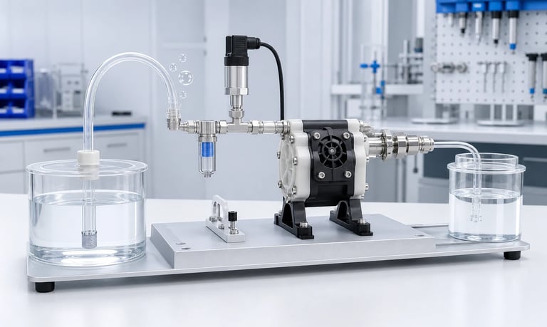
A diaphragm pump can lose suction when the inlet path admits air or becomes restricted, check valves fail to seal or open correctly, the diaphragm or chamber leaks, fluid and temperature conditions prevent filling, motor speed falls, or outlet pressure limits displacement.
Why Does a Diaphragm Pump Lose Suction?
A diaphragm pump creates suction by increasing the volume of its pumping chamber and reducing pressure at the inlet. The inlet valve must open, the outlet valve must seal, and the chamber must fill before the discharge stroke can move the medium forward.
If any part of that sequence is interrupted, the pump may fail to prime, lose flow after startup, draw bubbles, produce weak vacuum, or stop delivering under load. The pump itself is only one possible cause. Inlet tubing, fittings, reservoir venting, fluid properties, outlet pressure, motor speed, and measurement methods can create the same symptom.
The fastest route to a root cause is to define the failure state, test the pump with a controlled low-resistance setup, and then restore the production fluid path one component at a time.
Define the Suction Problem
"No suction" can describe several different conditions. Record exactly what the system does.
Common patterns include:
A dry liquid pump does not lift fluid during initial priming
The pump primes but later loses the liquid column
Bubbles appear continuously in the outlet
Flow falls as the reservoir empties
The pump works with water but not the production liquid
Vacuum is present at the inlet but little liquid is delivered
The pump works with an open outlet but not under pressure
Suction becomes weaker after warm-up or long operation
A gas pump reaches less vacuum than expected
The motor runs, but the diaphragm or crank mechanism does not move correctly
Note whether the problem is constant or intermittent and whether it depends on temperature, pump speed, reservoir level, orientation, outlet restriction, or time after idle.
Confirm that the flow direction matches the marked inlet and outlet. Reversed ports or incorrectly assembled valves can allow motor operation with little useful suction.
Distinguish Liquid-Pump and Gas-Pump Tests
Miniature diaphragm pumps can be designed for liquids, gases, or a specific combination. Do not assume a gas pump can reliably prime liquid or that a liquid pump can tolerate every gas-duty condition.
For a liquid pump, suction performance includes dry or wet prime behavior, liquid lift, bubble handling, chamber filling, and delivered flow. Fluid viscosity, surface tension, vapor pressure, valve wetting, and chemical compatibility matter.
For a gas pump, evaluate vacuum, pressure, leakage, humidity, condensation, gas density, and restriction. A vacuum reading at blocked flow does not establish gas flow through the application.
Use the intended medium and supplier-approved operating conditions. Procedures involving liquids can damage a pump intended only for dry gas, while an inappropriate gas leak test can exceed the pressure limits of a liquid path.
Verify the Measurement
Before disassembling the system, confirm that the suction loss is real.
Check:
Vacuum gauge type, range, accuracy, and zero
Whether pressure is reported as gauge or absolute
Sensor orientation and response time
Test tubing leakage and collapse
Flow-meter range and pressure loss
Sampling and digital filtering
Fluid temperature, density, and evaporation
Collection time and balance resolution
A blocked-inlet vacuum test, an open-flow test, and a suction-lift test measure different aspects of performance. Passing one does not guarantee the others.
For a blocked-inlet test, observe the pump and sensor limits and use a setup approved for the pump. For a flow test, keep the reference path short and adequately sized. For liquid lift, record the vertical distance from the liquid surface to the pump inlet, not merely the tube length.
Compare the suspect unit with a verified reference only when both use the same medium, voltage, speed, tubing, fittings, temperature, and test method.
Check for Inlet Air Leaks
An inlet leak is one of the most common reasons a liquid diaphragm pump fails to prime or draws bubbles. Under suction, air can enter a connection without liquid leaking outward.
Inspect:
Reservoir pickup and cap seal
Flexible tubing for cracks, hardening, or poor fit
Barbed, threaded, and compression fittings
Clamps and insertion depth
Filter housings and removable bowls
Selector valves and manifolds
Unused ports, sample branches, and sensor connections
Pump-port seals and adapters
Leakage may appear only at high speed, high suction lift, low reservoir level, or high viscosity because these conditions increase inlet vacuum.
Use a safe isolation or leak-test method appropriate to the assembly. Do not apply excessive pressure, vacuum, solvent, or heat to locate a leak. Temporarily replacing the production inlet with a short verified tube from a nearby reservoir can help separate an inlet-path leak from a pump problem.
Verify Reservoir Venting and Pickup Conditions
A rigid reservoir must admit replacement air as liquid leaves. A blocked or undersized vent can create increasing vacuum until pump flow falls or stops.
Check the vent under the actual fill level, cap, filter, orientation, and dispensing rate. Hydrophobic vent membranes can become wetted, contaminated, or blocked by condensation. A flexible bag or collapsible reservoir can also fail to collapse as intended if folded, clamped, or installed incorrectly.
At the pickup, confirm:
The inlet remains submerged
The pickup does not seal against the container wall or bottom
No vortex draws air at low level
Sediment or crystals do not block the opening
Return flow or agitation does not create foam near the inlet
The pickup tube does not kink as the container moves
Test with a full, typical, and nearly empty reservoir. A system that works only when full may have excessive suction lift, an inlet leak, or poor venting.
Reduce Inlet Restriction
The diaphragm chamber must fill during a limited part of every cycle. Excessive inlet resistance reduces filling and can make the pump appear to lose suction at higher speed.
Resistance increases with:
Long or small-bore tubing
Narrow fittings and manifold passages
Fine or loaded filters
Check valves with excessive opening pressure
Sharp bends, kinks, and sudden contractions
High suction lift
High fluid viscosity
Low fluid temperature
Soft tubing that collapses under vacuum
Measure vacuum near the pump inlet while operating. A high vacuum combined with low flow often points to upstream restriction. Little vacuum and no flow may instead suggest an air leak, valve problem, diaphragm leak, or drive fault.
Reduce one restriction at a time. Bypassing a protective filter can be useful only in a controlled diagnostic setup; restore required contamination protection before normal operation.
Inspect Inlet and Outlet Check Valves
Diaphragm pumps rely on one-way valves to direct each stroke. If the inlet valve does not open, the chamber cannot fill. If the outlet valve leaks backward, part of the discharge returns and reduces net suction and flow.
Valve problems can result from:
Particles, fibers, crystals, or dried residue
Sticky or curing fluid
Swelling, hardening, or chemical attack
Incorrect valve orientation
Warping or mechanical damage
Improper seating during assembly
Excessive opening pressure
Loss of elasticity after heat or aging
Gas bubbles or surface-tension effects
A valve can pass a simple visual inspection and still leak or respond slowly. Test opening, resealing, vacuum, pressure, and flow using a method representative of the pump cycle.
Do not clean a valve with an unapproved tool or chemical that can scratch the seat or change the elastomer. If service is allowed, follow the controlled procedure and record the component lot and orientation.
Inspect the Diaphragm and Pump Chamber
The diaphragm must flex through the intended stroke while sealing the pumping chamber from the drive side. Damage or reduced movement lowers displacement and suction.
Possible issues include:
Tear, pinhole, crack, or edge damage
Chemical swelling, stiffening, or softening
Permanent deformation
Incorrect assembly or clamp compression
Loose fasteners or chamber leakage
Reduced stroke from linkage wear
Contact with particles or sharp features
Condensation or liquid in an unintended cavity
External leakage may not be visible if the failure allows internal bypass or fluid entry into another part of the pump. Inspect any designed drain, vent, or leak-detection feature.
Do not reuse a diaphragm or seal unless the service procedure permits it. Fastener sequence and torque can affect chamber sealing and diaphragm movement.
For hazardous, reactive, biological, or contamination-sensitive media, isolate the equipment and follow the approved safety procedure before opening the pump.
Check Outlet Back Pressure
A diaphragm pump may generate inlet vacuum but deliver little flow when outlet pressure is too high. The motor and diaphragm spend more of each cycle compressing the chamber and overcoming the downstream load.
Inspect the outlet for:
Blocked or loaded filters
Closed or partially opening valves
Narrow nozzles
Kinked tubing
Unexpected elevation
Pressurized receiving containers
Crystals, particles, or dried deposits
A check valve installed backward
Measure outlet pressure close to the pump and at the process point where necessary. Capture transient peaks during valve switching or startup; a slow gauge may show only a lower average.
If the pump works into an open container but not through the production path, restore downstream components one at a time. Confirm that the required flow and pressure fall within verified system performance rather than a free-flow rating.
Evaluate Fluid Viscosity, Temperature, and Wetting
A pump that handles water may not prime or deliver the same flow with a viscous, volatile, foaming, or low-surface-tension fluid.
Higher viscosity slows chamber filling and increases line resistance. Cold fluid may be much more viscous than the room-temperature sample used during development.
Temperature can also change:
Diaphragm and valve flexibility
Seal dimensions
Fluid vapor pressure
Gas release and bubble formation
Chemical compatibility
Motor and driver behavior
Some valve and chamber surfaces wet differently after cleaning, long dry storage, or exposure to another fluid. Initial priming behavior may therefore differ from steady operation.
Record fluid identity, lot, concentration, preparation, age, viscosity, temperature, and bubble condition. If a substitute fluid is used, justify that it reproduces the properties relevant to suction and valve response.
Check for Cavitation, Vapor, and Outgassing
If local pressure falls sufficiently, vapor can form in the fluid. Dissolved gas may also come out of solution as pressure decreases. The resulting bubbles reduce chamber filling, create noise, and disturb flow.
Risk increases with high temperature, volatile fluid, excessive suction lift, inlet restriction, and high speed. Symptoms may include crackling noise, bubbles that appear downstream of a leak-free inlet, erosion, or flow that improves when inlet restriction is reduced.
Improve conditions by shortening and enlarging the inlet, reducing lift, lowering speed, controlling temperature, or positioning the pump closer to the source where appropriate.
Do not diagnose cavitation from sound alone. Valve chatter, trapped air, gears, bearings, and structural resonance can create similar noise.
Verify Motor, Drive, and Stroke
Hearing the motor does not prove that the diaphragm is completing the intended stroke. Verify mechanical motion and actual speed where safely observable.
Check:
Supply voltage at the pump during startup and load
Current limit and driver protection
PWM or analog command stability
Digital command and communication status
Motor speed feedback where available
Gear, eccentric, connecting rod, and bearings
Loose couplings or fasteners
Stall, intermittent contact, or thermal shutdown
High inlet vacuum or outlet pressure increases mechanical load. The motor may slow, current-limit, or cycle through protection.
Record command, voltage, current, actual speed, vacuum, pressure, and flow on the same time base. This makes it easier to see whether suction loss begins with a fluid restriction or a drive change.
Review Pump Orientation and Installation
Orientation can affect bubble clearance, valve movement, condensation drainage, and liquid retained in the chamber. Use only orientations approved for the exact pump and medium.
Check that:
Inlet and outlet ports are connected correctly
Pump mounting does not distort the housing
Fasteners use the approved sequence and torque
Tubing does not apply side load to the ports
Vibration isolators do not allow damaging movement
Heat sources do not raise pump or fluid temperature unexpectedly
Gas or drain ports remain open where required
An open-bench pump may work while the final enclosure traps heat or positions a gas pocket at a valve. Reproduce the installed orientation and routing during validation.
Consider Contamination and Idle Time
Many suction failures appear after the equipment has been idle. Fluid can dry, cure, crystallize, separate, settle, or leave residue on valve seats.
Define what happens during shutdown:
Is the pump left filled, flushed, drained, or dried?
Can fluid remain in dead volume?
Does cleaner mix with product residue?
Can particles settle against the inlet valve?
Does the fluid absorb or release gas?
What is the longest expected idle period?
Test the actual stop, storage, and restart sequence. A pump that restarts after a few minutes may fail after a weekend or seasonal shutdown.
Cleaning validation should verify that flow reaches the valves and chamber under representative conditions. Clear rinse fluid at the outlet does not by itself prove that sticky residue has been removed.
Use a Controlled Isolation Test
Isolate the system in a sequence that preserves evidence and avoids changing several variables at once.
Confirm motor command, voltage, current, and actual motion.
Verify the symptom with suitable vacuum and flow measurements.
Connect a short, airtight inlet tube to a nearby reservoir.
Discharge through a short, low-resistance outlet into an open receiver.
Test with the intended fluid at a controlled temperature.
Restore the production inlet components one at a time.
Restore the production outlet components one at a time.
Repeat at the reservoir level, temperature, speed, and pressure that produce the fault.
If the pump still fails in the controlled setup, inspect valves, diaphragm, chamber sealing, and drive mechanism according to the approved service procedure.
If performance returns, the cause is likely in the production routing, components, reservoir, fluid condition, or operating command.
Diaphragm Pump Suction Checklist
Symptom defined as failed prime, lost prime, bubbles, low flow, or low vacuum
Liquid or gas pump type and approved medium confirmed
Flow direction and port connections verified
Measurement range, units, zero, bandwidth, and restriction checked
Short reference inlet and outlet setup tested
Inlet tubing and fittings checked for air leaks
Reservoir vent, pickup depth, vortexing, and low-level state checked
Inlet vacuum measured under worst operating conditions
Tubing, fittings, valves, and filters checked for restriction
Inlet and outlet check valves inspected for contamination and damage
Diaphragm, chamber seals, and drive linkage evaluated
Outlet pressure and transient peaks measured
Fluid viscosity, temperature, surface behavior, and bubbles recorded
Suction lift, vapor formation, and outgassing reviewed
Voltage, current, motor speed, and thermal protection checked
Pump orientation, mounting, and port loads verified
Cleaning, idle, storage, and restart sequence reproduced
New and aged components tested as required
Failed parts and operating history retained for root-cause analysis
Common Suction Troubleshooting Mistakes
Replacing the pump before checking inlet fittings
Looking only for outward liquid leakage on a suction line
Testing with a full reservoir but not at low level
Ignoring a blocked reservoir vent
Comparing water performance with a viscous production fluid
Measuring vacuum but not flow, or flow but not pressure
Assuming motor sound means full diaphragm stroke
Cleaning valves with an unapproved tool or chemical
Increasing speed when chamber filling is already incomplete
Ignoring outlet restriction because the symptom appears at the inlet
Testing immediately after cleaning but not after long idle
Changing the pump, tubing, and valves at the same time
Using pressure units without stating gauge or absolute reference
Opening a contaminated pump without the required safety controls
Frequently Asked Questions
Why does my diaphragm pump run but not draw liquid?
Possible causes include an inlet air leak, blocked vent, excessive suction lift, inlet restriction, dry or contaminated valves, a leaking diaphragm chamber, reversed ports, or incomplete mechanical stroke.
Why does the pump lose prime after it stops?
Air may enter through an inlet connection, a check valve may leak, the liquid may drain because of elevation, or gas may form in the chamber. Test the stopped system over the actual idle period.
Can high outlet pressure reduce suction?
Yes. High back pressure can reduce net displacement, slow the motor, increase internal leakage, and prevent useful flow even when the inlet generates vacuum.
Why does a diaphragm pump work with water but not a thick liquid?
Higher viscosity increases inlet and outlet resistance and slows chamber filling and valve response. Test the actual fluid across its full temperature range.
How can I find a suction-side air leak?
Use a safe, validated leak or isolation test and replace the inlet temporarily with a short verified path. A suction leak may draw air without leaking liquid outward.
When should diaphragm valves or the diaphragm be replaced?
Follow the validated service limit for the exact pump, fluid, pressure, temperature, speed, and duty cycle. Replace components earlier if leakage, damage, or performance reaches the defined rejection criterion.
Kamoer Diaphragm Pump Troubleshooting Support
Kamoer can help evaluate inlet vacuum, suction lift, tubing and fittings, valve behavior, diaphragm condition, outlet pressure, fluid properties, motor control, installation, and representative testing for miniature diaphragm pump systems.
Related Stories
Kamoer Fluid Tech (Shanghai) Co., Ltd.
pump@kamoer.com