

Why Are There Air Bubbles in My Pump Tubing
TROUBLESHOOTING & FAQS
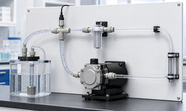
Air bubbles in pump tubing may enter through suction-side leaks or the reservoir, remain after incomplete priming, form when dissolved gas leaves the liquid, grow under low inlet pressure, or collect in fittings, sensors, valves, filters, and high points in the fluid path.
Why Are There Air Bubbles in My Pump Tubing?
Air bubbles in pump tubing can reduce flow, disturb dosing, delay pressure response, make sensors unstable, create noise, and leave liquid dripping after the motor stops. The bubbles may enter through a leak, arrive from the reservoir, remain after incomplete priming, or form inside the liquid as pressure and temperature change.
The correct fix depends on the source. Tightening every fitting will not remove gas released from solution, and running the pump faster may worsen bubbles caused by inlet restriction. A structured diagnosis should track where the first bubble appears and under which operating condition.
Peristaltic and diaphragm pumps respond differently to gas, but both require an airtight, adequately sized inlet path and a priming process that clears trapped volume.
Define the Bubble Symptom
Record what the bubbles look like and when they appear.
Useful observations include:
First location where gas becomes visible
Individual small bubbles, long gas segments, or foam
Continuous or intermittent appearance
Startup only or throughout operation
Dependence on pump speed
Dependence on reservoir level
Change with fluid temperature
Appearance after a filter, valve, sensor, or fitting
Movement during pump stop or reversal
Whether the pump loses prime
Measure the effect on flow, dose, inlet vacuum, outlet pressure, and sensor output. A few small bubbles may be acceptable in a transfer line but unacceptable in an analytical cell or microliter-scale dose.
Distinguish gas from an empty transparent section caused by drainage or siphoning. Also confirm that apparent bubbles are not immiscible droplets, foam, particles, or optical reflections from the tube wall.
Find Where the First Bubble Appears
The first visible bubble is often close to the source, but gas may become visible only after pressure falls or small bubbles combine.
Use transparent tubing in a controlled diagnostic setup where material and safety requirements allow. Inspect the path in order:
Reservoir and pickup
First inlet connection
Filter, valve, and manifold
Pump inlet
Pump outlet
Sensors and dampers
Nozzle or receiving point
If bubbles are present before the pump, investigate the reservoir, inlet leaks, outgassing, and restrictions. If the inlet is bubble-free but gas appears at the outlet, review pump priming, internal chamber behavior, low-pressure formation, and gas trapped in downstream components.
Use synchronized video and pressure data for intermittent faults. A bubble may appear only during a particular roller position, diaphragm stroke, valve event, or speed change.
Check for Suction-Side Air Leaks
An inlet connection can draw air inward under vacuum without leaking liquid outward. This is a common reason bubbles appear only while the pump runs.
Inspect:
Tube-to-barb insertion depth
Compression fittings and ferrules
Clamps and pinch points
Cracked, hardened, swollen, or undersized tubing
Threaded fittings and seals
Filter housings
Selector valves and manifolds
Reservoir caps and pickup tubes
Sample ports and unused branches
Pump-port seals
Leakage may worsen at higher speed, lower reservoir level, higher viscosity, or colder fluid because inlet vacuum increases.
Use a leak or isolation method appropriate to the materials and pressure limits. Replacing the production inlet temporarily with a short verified tube from a nearby reservoir can help determine whether the bubble source is upstream of the pump.
Do not apply excessive positive pressure or vacuum to components designed only for low-pressure liquid service.
Check Reservoir Venting and Pickup Design
A rigid reservoir must admit replacement air as liquid is removed. A blocked vent creates increasing vacuum and may cause low flow, container deformation, air entry at seals, or intermittent prime loss.
Check:
Vent opening and flow capacity
Hydrophobic membrane wetting or contamination
Condensation blocking the vent
Flexible bag folds or collapse behavior
Cap and pickup seals
Pickup depth at low liquid level
Vortex formation
Return flow or agitation near the pickup
Foam or floating material
Keep the pickup submerged through the specified operating range. Avoid placing it where agitation entrains air or where it can seal against the container wall or bottom.
Test full, typical, and nearly empty reservoir states. Bubbles that appear only near empty may result from vortexing, intermittent exposure of the pickup, higher suction lift, or increased inlet leakage.
Remove Bubbles Introduced During Filling
Air can remain in new tubing, filters, sensors, manifolds, pump chambers, and high points after assembly or fluid replacement.
A good filling design provides a continuous gas escape route. Review orientation and flow direction through:
Filter housings
Pressure and flow sensors
Diaphragm chambers
Valves
Pulsation dampers
Tees and manifolds
Enlarged fittings
Vertical loops
Large cavities with top ports may trap gas if filled from the wrong direction. A component can appear full while a pocket remains above the main flow.
Define a production priming sequence, not an informal operator technique. The sequence should state reservoir state, pump speed, valve position, flow direction, duration, waste handling, and the criterion for completed prime.
If manual tapping or tilting is required, redesign the orientation or document a controlled fixture and method.
Validate the Priming Speed
Fast priming is not always the most reliable priming.
At excessive speed, inlet vacuum rises and a peristaltic tube or diaphragm chamber may not refill completely. The pump can pull small leaks, draw a reservoir vortex, or create low-pressure gas formation.
At very low speed, the pump may not generate enough pressure or valve motion to clear gas from high points and restrictions.
Test a range of prime speeds while measuring:
Time to first liquid
Time to bubble-free outlet
Inlet vacuum
Outlet pressure
Motor current
Fluid consumed during prime
Success after dry and partial prime
Use a defined timeout and fault response. Unlimited priming can empty a source, overfill waste, heat the pump, or run an unsuitable pump dry.
The validated prime speed may differ from the normal dosing or transfer speed.
Reduce Excessive Inlet Restriction
High inlet resistance lowers pressure at the pump and can encourage air entry, tube collapse, incomplete chamber filling, outgassing, or vapor formation.
Common restrictions include:
Long small-bore tubing
Narrow fittings
Fine or loaded filters
Check valves with high opening pressure
Sharp bends and kinks
Excessive suction lift
Sticky or viscous fluid
Cold fluid
Soft tubing that collapses
Measure inlet vacuum close to the pump at the worst speed, temperature, viscosity, reservoir level, and filter condition.
Improve the path by shortening it, increasing internal diameter, removing unnecessary fittings, using a suitable filter area, placing the pump closer to the source, and selecting tubing that resists collapse.
Do not remove required contamination protection permanently. If a filter is bypassed for diagnosis, restore a validated protective solution before normal use.
Understand Dissolved Gas and Outgassing
Liquids can contain dissolved air or another gas that is invisible at reservoir pressure. When pressure falls at the pump inlet, the gas may leave solution and form bubbles.
Outgassing depends on:
Dissolved-gas content
Pressure reduction
Temperature
Fluid composition
Residence time
Surface roughness and nucleation sites
Agitation and mixing
Freshly mixed, shaken, warmed, pressurized, or refrigerated fluids may release gas differently after preparation.
If an airtight short inlet still produces bubbles as pressure falls, compare degassed and untreated fluid under the same conditions. Record fluid preparation and time after mixing.
Degassing may use vacuum, membrane, settling, controlled heating or cooling, or another process appropriate to the fluid. The method must not evaporate important components, change concentration, contaminate the product, or damage sensitive material.
Check Vapor Formation and Cavitation-Like Behavior
If local liquid pressure approaches its vapor pressure, vapor bubbles can form. Volatile fluids and warm liquids are more sensitive.
Risk increases with:
High temperature
High pump speed
Large suction lift
Restricted inlet
Narrow fittings
Loaded filters
Volatile solvents or mixtures
Symptoms may include crackling noise, bubbles that appear downstream of a leak-free inlet, unstable flow, and improvement when speed or inlet restriction is reduced.
Do not diagnose vapor formation from sound alone. Valve chatter, tube motion, gears, trapped air, and structural vibration can sound similar.
Review the exact fluid vapor behavior and safety requirements. Lowering inlet restriction and temperature or relocating the pump may help, but any change must preserve product stability and process conditions.
Consider Temperature Changes
Temperature affects both gas solubility and fluid viscosity. Warming can cause dissolved gas to leave solution, while cooling may increase viscosity and inlet vacuum.
Temperature also changes:
Peristaltic tube recovery
Diaphragm and valve flexibility
Seal dimensions
Vapor pressure
Fluid density
Sensor readings
Pump and driver behavior
Measure fluid temperature near the pump inlet and outlet. Record pump-head and enclosure temperature during warm-up.
Bubbles that increase during operation may result from local motor or enclosure heating rather than a changing leak. Bubbles that occur only at cold startup may result from viscosity and incomplete refill.
Test the full operating and storage temperature range, including transitions rather than only stabilized endpoints.
Review Pump-Type Behavior
Peristaltic Pumps
Peristaltic pumps can move gas and liquid because the tube is mechanically occluded, but bubbles reduce the liquid volume inside each trapped segment. Large gas sections compress under outlet pressure and delay liquid delivery.
Check tube recovery, inlet vacuum, occlusion, speed, and tube condition. A worn or incorrectly installed tube may permit backflow or poor prime.
Diaphragm Liquid Pumps
Diaphragm liquid pumps depend on chamber filling and check-valve sealing. Gas can compress inside the chamber instead of opening the outlet valve, especially against pressure.
Check inlet leaks, valve contamination, valve wetting, chamber orientation, diaphragm condition, prime speed, and outlet back pressure.
Use a pump intended for the medium and operating state. A liquid pump's ability to pass a small bubble does not prove it can run dry indefinitely, and a gas pump may not tolerate liquid carryover.
Check Outlet Pressure and Compliant Volume
Bubbles are compressed by outlet pressure. A gas segment may appear smaller under pressure and expand again after the restriction or after the pump stops.
This can cause:
Delayed dose delivery
Sensor oscillation
Pressure lag
Post-stop dripping
Different bubble size along the line
Stored liquid release
Inspect outlet filters, valves, nozzles, long tubing, elevation, and pressurized receivers. Measure pressure close to the pump and at the process-critical point.
A pulsation damper or soft tubing adds compliance. These components may smooth pressure but can trap gas and increase settling time.
Remove bubbles before using compliance as a deliberate damping method. Uncontrolled gas pockets vary with pressure, temperature, orientation, and time.
Optimize Tubing Routing
High points and large cavities can trap gas. Low points can retain liquid during drain and create gas-liquid segments on restart.
Design routing to:
Rise or fall continuously where appropriate
Avoid unnecessary loops
Keep bends above the minimum radius
Prevent kinks and tube flattening
Support tubing without crushing it
Keep fittings oriented for gas escape
Minimize dead legs
Make trapped-gas locations visible or serviceable
Tube diameter also matters. A larger bore may pass bubbles with lower resistance but increases internal volume. A small bore may trap or elongate gas and create higher pressure loss.
Validate the final product orientation, including tilt, transport, door opening, and movable nozzles. Routing that clears gas on a bench may trap it inside the assembled product.
Review Valves, Filters, Sensors, and Dampers
Any component with a chamber or narrow passage can collect gas or create low pressure.
For each component, check:
Internal volume and flow path
Recommended orientation
Opening pressure or restriction
Venting during prime
Bubble sensitivity
Wetting behavior
Drainability
Cleaning and replacement
Flow sensors may report unstable values when gas crosses the measurement region. Pressure sensors with trapped bubbles may respond slowly. Filters can retain gas on their upstream side or release bubbles after pressure changes.
An automatic air vent may be appropriate in some systems, but it introduces another seal, possible contamination path, fluid loss, and maintenance item.
Use components designed and validated for the fluid, pressure, cleanliness, and orientation requirements.
Prevent Foam and Air Entrainment
Foam is a gas-liquid dispersion that may not behave like a few discrete bubbles. Surfactants, proteins, detergents, mixing, splashing, and high-velocity return flow can stabilize foam.
Reduce entrainment by:
Keeping return flow below the liquid surface where appropriate
Reducing unnecessary free fall and splashing
Separating return and pickup locations
Controlling agitation speed
Avoiding a vortex
Allowing validated settling time
Using reservoir geometry that separates gas
Do not add an antifoam agent without confirming product, process, material, regulatory, and analytical compatibility.
Measure the liquid fraction delivered, not only total foam volume. A pump can move a repeatable foam volume while delivering an inconsistent liquid dose.
Test the actual formulation and preparation process because water may not reproduce foam behavior.
Use Degassing and Bubble Separation Carefully
When fluid preparation cannot prevent gas, the system may need a degassing or separation stage.
Options can include:
Settling reservoir
Gas-permeable membrane degasser
Vacuum degassing
Bubble trap
Centrifugal or gravity separator
Controlled vent chamber
Each option introduces tradeoffs involving internal volume, pressure loss, evaporation, contamination, material compatibility, cleaning, maintenance, and response time.
A bubble trap must be oriented and sized for expected gas load and flow. It can become a dead volume or overflow source if not monitored.
Membrane degassing depends on fluid, gas, pressure, membrane material, temperature, and contact area. It may remove volatile product components as well as air.
Validate the complete device rather than relying on a generic degassing claim.
Check Dosing and Calibration Effects
Gas reduces the liquid fraction in the pump path and stores compression energy. A motor command that normally produces a fixed liquid dose may deliver less liquid, delay the dose, or release fluid after stop.
During validation, record:
Individual dose mass or volume
Bubble size and position
First dose after prime or idle
Outlet pressure
Valve and suck-back timing
Delay between motor movement and liquid output
Post-stop dripping
Do not recalibrate over an unstable bubble condition. A new coefficient may correct one average while the gas fraction continues to vary.
Establish a bubble-free or controlled-gas state first. If occasional gas is unavoidable, define detection, discard, re-prime, or closed-loop recovery.
Motor position and current cannot prove that liquid was delivered. Use fluid, weight, pressure, optical, or level feedback where justified by risk.
Use a Structured Troubleshooting Sequence
Change one variable at a time and preserve the failed configuration.
Confirm the bubbles with visual and flow or dose data.
Identify the first location and operating condition where they appear.
Test a short verified inlet from a nearby reservoir.
Confirm reservoir venting and pickup submergence.
Reduce prime and operating speed while measuring inlet vacuum.
Bypass one restrictive component at a time in a controlled setup.
Compare untreated and suitably degassed fluid.
Test temperature, reservoir level, and outlet pressure extremes.
Restore production components one at a time.
Verify the final sequence after idle, cleaning, and power cycling.
Record every change. Replacing the pump, tubing, filter, and fittings simultaneously may remove the symptom but lose the root cause.
Retain suspect fittings, tubing, valves, and filters for inspection.
Bubble Troubleshooting Checklist
Bubble type, first location, timing, and effect documented
Suction-side tube, fittings, seals, filters, and valves leak-checked
Reservoir vent and flexible-container behavior verified
Pickup remains submerged without vortex or foam
Production fill and prime sequence reproduced
Prime speed tested for bubble clearance and inlet vacuum
Inlet tubing length, diameter, lift, and restrictions reviewed
Loaded filters and valve opening pressure included
Dissolved gas, fluid preparation, and outgassing evaluated
Vapor formation reviewed with temperature and inlet pressure
Peristaltic tube recovery or diaphragm valve behavior checked
Outlet pressure and compliant stored volume measured
Tubing routing, component orientation, and high points inspected
Sensors, dampers, filters, and manifolds checked for trapped gas
Foam and reservoir return flow controlled
Degasser or bubble trap tradeoffs validated where used
Dose, flow, pressure, and post-stop behavior verified
Long idle, cleaning, reservoir replacement, and power cycle tested
Multiple pump and component samples included
Common Bubble Troubleshooting Mistakes
Looking only for outward liquid leaks
Increasing pump speed without measuring inlet vacuum
Treating all bubbles as inlet leaks
Ignoring a blocked reservoir vent
Priming only with a full reservoir
Testing water when the product outgasses or foams differently
Measuring room temperature instead of fluid temperature
Assuming a clear pump inlet means no dissolved gas
Adding a bubble trap without checking dead volume and cleaning
Using a pulsation damper as an uncontrolled air chamber
Recalibrating instead of stabilizing the fluid path
Changing several components at once
Verifying steady operation but not first use after idle
Using motor motion as proof of liquid delivery
Frequently Asked Questions
Why do bubbles appear only when the pump runs?
The operating pump creates inlet vacuum that can draw air through a small leak, release dissolved gas, collapse tubing, or lower pressure enough for vapor bubbles to form.
Can a fitting leak air without leaking liquid?
Yes. A suction-side joint may admit air under vacuum while showing no outward liquid leak when the pump is stopped.
Why do bubbles increase at high pump speed?
Higher speed can increase inlet vacuum, vortexing, incomplete refill, air leakage, outgassing, and vapor formation. It can also give trapped gas less time to escape.
Can peristaltic pumps pass air bubbles?
They often can move gas-liquid segments, but bubbles reduce liquid per cycle, compress under pressure, delay dosing, and may disturb sensors. Acceptability depends on the process.
Should I add a bubble trap?
Only after identifying the source. A trap can help with unavoidable gas but adds volume, pressure loss, cleaning needs, orientation limits, and possible contamination or overflow risks.
How can bubbles be detected automatically?
Options include optical bubble sensing, flow or pressure analysis, weight, reservoir level, or process feedback. Detection limits and response should match the smallest consequential gas volume.
Kamoer Bubble Troubleshooting Support
Kamoer can help evaluate inlet leaks, pump type, tube or valve behavior, reservoir design, priming, fluid properties, pressure, routing, sensing, and representative bubble tests for OEM liquid-pump systems.
Related Stories
Kamoer Fluid Tech (Shanghai) Co., Ltd.
pump@kamoer.com