

What Is Back Pressure in a Peristaltic Pump
MICRO PUMP BASICS
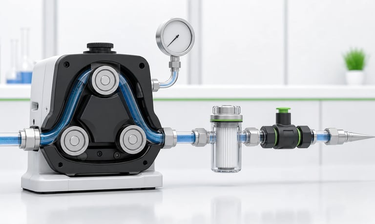
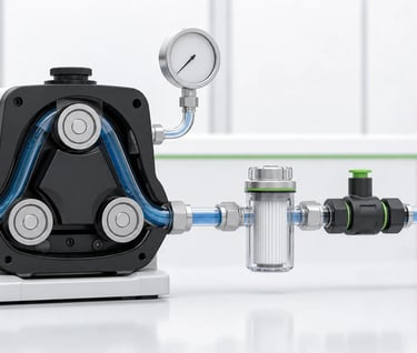
This article explains back pressure in a peristaltic pump system, including its common causes, effects on flow and dosing, tubing and motor risks, measurement methods, troubleshooting steps, and practical ways to reduce downstream resistance.
What Is Back Pressure in a Peristaltic Pump?
Back pressure is the resistance a pump must overcome on its discharge side. In a peristaltic system, it can come from tubing, filters, valves, nozzles, elevation, fluid viscosity, or pressure inside the receiving process.
Some resistance is normal. Problems begin when the operating pressure approaches or exceeds what the selected pump head, tubing, motor, and connections can handle. Flow may decrease, dosing may drift, tubing may move or wear faster, and motor current or temperature may rise.
Back pressure should therefore be treated as a property of the complete fluid path, not as a pump specification alone.
How a Peristaltic Pump Creates Pressure
Rollers compress flexible tubing against a track and move the compression point toward the outlet. Fluid trapped ahead of the roller is displaced downstream.
To prevent reverse leakage, the tube must close sufficiently at the compression point. This is called occlusion. The motor must also provide enough torque to compress the tube and push the liquid against downstream resistance.
Pressure capability depends on:
Pump-head and track geometry
Tubing material, dimensions, and hardness
Degree of occlusion
Roller condition and alignment
Motor torque and speed
Fluid viscosity and temperature
Tube retention and connector design
Operating duty cycle
For this reason, a pressure value from one tube or speed should not automatically be applied to another configuration.
Common Sources of Back Pressure
Narrow or Long Discharge Tubing
Friction increases as liquid travels through a tube. Smaller inner diameter, greater length, higher flow, and higher viscosity increase the pressure loss.
Filters
A clean filter adds resistance, and loading during use can increase it further. A pump that works during initial testing may lose flow as the filter collects particles.
Check Valves and Flow Sensors
Check valves require opening pressure and create additional loss during flow. Sensors, manifolds, and fittings may contain small internal passages that restrict the system.
Nozzles and Orifices
A narrow dispensing tip can create substantial resistance, particularly with viscous liquid or a short dosing time.
Elevation
Pumping upward requires pressure to raise the liquid. The vertical difference between pump and outlet should be included in the operating condition.
Pressurized Destination
If the pump discharges into a vessel or process already under pressure, it must overcome that pressure before flow begins.
Fluid Viscosity
Viscous liquids create more resistance through tubing and components. Viscosity may also change with temperature, concentration, or shear.
Blockage or Kinked Tubing
Crystals, dried fluid, particles, closed valves, pinched tubing, and assembly errors can create sudden excessive back pressure.
How Back Pressure Affects Flow
Peristaltic pumps are positive-displacement devices, but delivered flow is not completely independent of pressure.
As back pressure rises, the tube may expand slightly between rollers, fluid may slip past an incompletely closed compression point, and the motor may slow under load. Actual delivered volume per revolution can decrease.
The effect may become more pronounced with worn tubing, insufficient occlusion, high speed, a low-torque motor, or elevated temperature.
Use flow data measured at the intended pressure. Free-flow performance is not a reliable dosing value for a restricted system.
How Back Pressure Affects Dosing Accuracy
A calibrated dose can change when downstream resistance changes. Common causes include a filter loading over time, a valve opening inconsistently, a nozzle becoming partially blocked, or a process vessel changing pressure.
For repeatable dosing:
Calibrate with the final fluid path.
Test minimum and maximum expected pressure.
Monitor components whose resistance changes with use.
Recalibrate after tube or fluid-path replacement.
Consider pressure or flow feedback for critical applications.
Accuracy should be specified across an operating range rather than at one bench condition.
Effects on Tubing and Connections
Higher discharge pressure increases mechanical stress on the tube and fittings.
Possible results include:
Faster tube fatigue
Permanent flattening or deformation
Tube swelling between rollers
Tube walking through the pump head
Leakage at fittings
Tube rupture in severe cases
Reduced recovery and suction
Use only tubing dimensions and materials approved for the pump head. Secure the tube correctly and keep external routing free from tension.
Effects on the Motor and Drive
The motor must provide torque for both tube compression and fluid pressure. Additional load may increase current, temperature, noise, and speed variation.
Continuous operation near a high-load condition can affect the motor, gearbox, bearings, driver, and enclosure temperature. Test the final voltage, control method, speed, mounting, and duty cycle.
A stalled or blocked outlet should be included in fault analysis where it is reasonably possible.
How to Measure Back Pressure
Install a suitable pressure sensor or gauge near the pump outlet. Place it so that the measured point represents the pressure experienced by the pump without adding excessive dead volume or restriction.
Record pressure together with:
Actual flow or dose
Motor speed and control signal
Supply voltage and current
Fluid and ambient temperature
Tubing type and hours of use
Filter condition
Reservoir and outlet elevation
Measure during the complete dosing event. Short pressure peaks may be missed by a slow instrument.
The sensor range, wetted materials, response time, and accuracy must suit the application.
How to Estimate Pressure Loss
Engineering calculations can help identify likely restrictions, especially for straight tubing and known fluids. However, small fittings, flexible tubes, valves, pulsation, non-Newtonian liquids, and changing temperature can make a simple calculation incomplete.
Use calculations for initial design, then verify the assembled system with the actual liquid and components.
When comparing layouts, pay particular attention to:
Tube inner diameter and length
Number of bends and fittings
Smallest internal passage
Filter area and expected loading
Valve opening pressure
Nozzle diameter
Flow and viscosity range
Vertical height
How to Reduce Back Pressure
Increase Discharge Tube Diameter
A larger internal diameter can reduce friction, provided it remains compatible with the required connectors, dose volume, and equipment space.
Shorten the Fluid Path
Remove unnecessary tubing length, sharp bends, and redundant fittings. Keep routing maintainable and mechanically safe.
Select Lower-Resistance Components
Use appropriately sized filters, valves, sensors, manifolds, and nozzles. Confirm performance after expected filter loading.
Reduce Pump Speed
Lower instantaneous flow can reduce pressure loss in a restrictive path. The dosing time must still meet the application requirement.
Control Fluid Temperature Where Appropriate
If the process permits, maintaining a stable temperature can reduce viscosity variation. Do not heat a fluid without confirming safety, compatibility, and process requirements.
Prevent Deposits and Blockage
Use flushing, purging, filtration, or cleaning procedures suited to the medium. Design low points and dead zones carefully when crystallization is possible.
Select a More Suitable Pump Configuration
If the required operating pressure remains outside the practical range, use a different tube, pump head, motor, or pump technology validated for that condition.
Back Pressure Test Procedure
Assemble the intended reservoir, inlet line, pump, discharge line, valves, filter, sensor, and nozzle.
Install new approved tubing according to the pump procedure.
Prime the system with the actual liquid.
Measure flow, pressure, current, temperature, and noise at the typical condition.
Test the minimum and maximum expected downstream resistance.
Repeat at relevant speeds, temperatures, and reservoir levels.
Run a representative duty cycle and monitor tube movement and flow drift.
Repeat with aged tubing and a loaded filter where applicable.
Test a blocked or closed outlet only under an approved fault-test procedure.
Define operating limits and software responses from the results.
Warning Signs of Excessive Back Pressure
Flow or dose decreases unexpectedly
Motor current or temperature rises
Pump speed becomes unstable
Tubing moves in the head
Connections begin to leak
Tube wear accelerates
Noise or vibration increases
Pressure spikes during each roller event
A filter or nozzle blocks repeatedly
Stop and inspect the system if leakage, tube damage, or abnormal motor load occurs.
Common Mistakes
Selecting from free-flow data only
Ignoring filter loading
Using water tests for a viscous fluid
Assuming every tube has the same pressure capability
Measuring pressure far from the pump
Missing short pressure peaks
Increasing occlusion without checking tube life and motor load
Treating a blocked outlet as normal operation
Calibrating before the final valves and nozzle are installed
Frequently Asked Questions
Does back pressure always reduce peristaltic pump flow?
The effect depends on pump design, tube, speed, motor torque, and pressure level. As resistance rises, delivered flow commonly decreases and variability may increase.
Can I increase tube compression to handle more pressure?
Additional occlusion may reduce slip in some designs, but it can also increase motor load, heat, and tube wear. Use only adjustments and limits approved for the pump head.
Does a check valve increase back pressure?
Yes. It requires opening pressure and creates flow resistance. Select and test it at the actual flow, viscosity, orientation, and temperature.
Why does flow decrease as a filter becomes dirty?
Collected material increases filter resistance. The pump then operates at a higher back pressure, which can reduce delivered flow and increase load.
Can back pressure shorten tubing life?
Yes. Higher pressure can increase tube stress, expansion, heat, movement, and fitting load. Actual life should be established through representative testing.
Where should a pressure sensor be installed?
It is generally useful near the pump outlet, before major downstream restrictions, but the correct location depends on what the system needs to monitor. Avoid adding an unsuitable restriction or dead volume.
Kamoer Application Support
Back pressure is a system condition created by the pump, tubing, liquid, fittings, valves, filters, nozzle, and destination. Reliable selection requires the intended operating point and worst expected restriction to be tested together.
Kamoer develops micro peristaltic pumps, diaphragm pumps, laboratory pumps, and customized OEM fluid-transfer solutions. Kamoer can help evaluate flow, pressure, tubing, motor control, duty cycle, and system layout for a dosing or transfer application.
Share your fluid path and operating requirements with Kamoer to begin a pump and back-pressure review.
Related Stories
Kamoer Fluid Tech (Shanghai) Co., Ltd.
pump@kamoer.com