

Vacuum vs Pressure: How to Read Diaphragm Gas Pump Data
MICRO PUMP BASICS
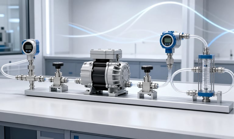
Diaphragm gas pump data must be interpreted using the correct pressure reference, units, inlet and outlet conditions, gas, temperature, voltage, and duty cycle because free flow, ultimate vacuum, shutoff pressure, and rated operating points describe different tests rather than one simultaneous capability.
Vacuum vs Pressure: How to Read Diaphragm Gas Pump Data
A diaphragm gas pump can draw gas through its inlet to create vacuum, discharge gas through its outlet to create positive pressure, or operate with restrictions on both sides. The same pump may therefore have vacuum, pressure, and flow data that look similar but describe different test conditions.
The largest vacuum value, highest pressure value, and maximum flow value usually do not occur at the same operating point. Free-flow data are measured with little restriction. Ultimate vacuum is approached as inlet flow falls. Shutoff pressure is measured as outlet flow approaches zero.
Correct selection requires the full performance curve, the pressure reference and units, the gas and temperature, the supply voltage, and the actual inlet and outlet restrictions of the OEM system.
Identify the Pressure Reference
Pressure values are meaningful only when their reference is known.
Absolute Pressure
Absolute pressure is referenced to a perfect vacuum. It cannot be negative. Local atmospheric pressure is therefore an absolute value that changes with altitude and weather.
Gauge Pressure
Gauge pressure is referenced to the local atmosphere. Positive gauge pressure is above atmosphere. Negative gauge pressure is below atmosphere and may be reported as vacuum.
The relationship is:
Gauge pressure = absolute pressure - local atmospheric pressure
Vacuum Reading
Vacuum may be expressed as the amount below local atmospheric pressure:
Vacuum reading = local atmospheric pressure - inlet absolute pressure
Some documents instead state the remaining absolute pressure. These two descriptions move in opposite numerical directions as vacuum improves. A larger vacuum gauge reading corresponds to a lower absolute pressure.
Never compare a negative gauge value directly with a positive absolute value without converting them to the same reference and local atmospheric condition.
Check the Units
Diaphragm gas pump data may use:
Pa or kPa
mbar or bar
psi
mmHg or Torr
inHg
A percentage of vacuum
The pressure reference still matters after the unit is identified. For example, kPa absolute and kPa gauge are not interchangeable.
Percentage vacuum can be ambiguous if the atmospheric reference and formula are not stated. It also changes in interpretation with local atmospheric pressure.
Keep calculations in one consistent unit system. Record whether every value is absolute, gauge, vacuum relative to atmosphere, or differential.
Avoid copying a number without its sign and reference. A specification database field labeled only "pressure" can create serious selection errors.
Understand Free Flow
Free flow is the gas flow when inlet and outlet restrictions are minimized under a defined test setup. It is often the largest flow value shown for a pump.
Free-flow conditions may include:
Inlet near atmospheric pressure
Outlet near atmospheric pressure
Short, adequately sized test tubing
Defined gas and temperature
Defined supply voltage or speed
An OEM system rarely operates at true free flow. Filters, tubing, valves, sensors, fittings, sampling probes, silencers, condensers, and elevation create pressure loss.
Do not select a pump because its free-flow value equals the required system flow. Find the required flow at the real inlet vacuum and outlet pressure.
Test-fixture restriction can also reduce the reported value. Compare pumps only when methods and conditions are sufficiently similar.
Understand Ultimate Vacuum
Ultimate vacuum is the lowest inlet absolute pressure, or the largest vacuum relative to atmosphere, that the pump approaches under a defined blocked or nearly blocked inlet test.
At this condition, useful inlet flow is very low. Leakage, valve behavior, diaphragm displacement, dead volume, gas compression, temperature, speed, and measurement setup determine the result.
Ultimate vacuum does not mean the pump can deliver its maximum flow while maintaining that vacuum. It is an endpoint of the vacuum-flow curve.
When the application needs a flow at vacuum, such as gas sampling, specify both:
Required inlet pressure or vacuum
Required flow at that inlet condition
Also define outlet pressure. A pump exhausting to atmosphere may behave differently from one that must overcome a silencer, valve, long line, or pressurized chamber.
Understand Shutoff or Maximum Pressure
Shutoff pressure is approached when the outlet is blocked and flow falls toward zero. It is an endpoint of the pressure-flow curve.
This value should not automatically be treated as a recommended continuous operating pressure. Blocked-outlet operation can increase diaphragm load, valve stress, motor current, driver load, leakage, temperature, and acoustic noise.
Ask whether the published pressure is:
A short test endpoint
A continuous operating limit
A protective switch setting
A structural pressure limit
A value at a defined flow
The system operating point should stay within the supplier-approved region for pressure, flow, duty cycle, voltage, and temperature.
If blockage is foreseeable, define current, pressure, temperature, timeout, shutdown, and recovery behavior separately from normal operation.
Read the Vacuum-Flow Curve
A vacuum-flow curve shows how inlet flow changes as inlet pressure falls below atmosphere. The horizontal and vertical axes may be arranged differently, so read their labels carefully.
Typical interpretation:
Near atmospheric inlet pressure, available flow is highest.
As inlet pressure decreases, the pump must expand lower-pressure gas and overcome a larger pressure ratio.
Flow usually decreases as the pump approaches ultimate vacuum.
Find the required vacuum on the correct axis, move to the curve for the intended voltage or speed, and read the corresponding flow. Then confirm the outlet condition used for that curve.
If the application's outlet is above atmosphere, a curve measured with atmospheric discharge may overstate performance.
Curves may represent typical values rather than guaranteed unit limits. Ask how production variation and acceptance limits are handled.
Read the Pressure-Flow Curve
A pressure-flow curve shows how outlet flow changes as discharge pressure rises above the reference condition.
Typical interpretation:
Near atmospheric outlet pressure, available flow is highest.
As outlet pressure rises, valve leakage, gas compression, motor load, and diaphragm behavior reduce delivered flow.
At shutoff pressure, useful flow approaches zero.
Find the required outlet pressure and read flow from the correct curve. Confirm the inlet condition. A pressure curve measured with atmospheric inlet does not describe a restricted suction line.
If the application has both inlet vacuum and outlet pressure, request combined-condition data or test the complete system. Do not subtract separate catalog endpoints and assume the result is valid.
Use Differential Pressure Carefully
The diaphragm works against a pressure difference between outlet and inlet, but pump performance is not determined by differential pressure alone.
For a simplified comparison:
Pump differential pressure = outlet absolute pressure - inlet absolute pressure
Two systems can have the same differential pressure but different absolute inlet and outlet pressures. Gas density, compression ratio, leakage, valve behavior, volumetric flow, and motor load may differ.
For example, a pump moving gas from below atmosphere to atmosphere is not necessarily equivalent to moving gas from atmosphere to the same differential pressure above atmosphere.
Use full inlet and outlet absolute conditions when requesting performance data. Differential pressure is useful, but it should not replace both boundary pressures.
Distinguish Volumetric and Mass Flow
Gas volumetric flow depends on pressure and temperature. The same mass of gas occupies a different volume at different conditions.
Ask whether flow is reported as:
Actual volumetric flow at the measurement condition
Standardized or normalized volumetric flow
Mass flow
If a standard or normal flow unit is used, the reference temperature and pressure must be stated. Different conventions can produce different numerical volumes for the same mass flow.
A flow meter may display standardized flow while a pump curve reports actual flow, or the reverse. Convert on a consistent basis before comparison.
For sampling applications, decide whether the process requirement is actual volume through a probe, mass flow, standardized volume, or exchange rate in a chamber.
Check the Test Gas
Air is commonly used for pump data, but another gas may change performance and compatibility.
Relevant gas properties include:
Density
Viscosity
Molecular size and leakage behavior
Humidity and condensation
Chemical compatibility
Flammability, toxicity, or reactivity
Particle or aerosol content
Valve response, leakage, motor load, flow-meter calibration, and heat transfer can change with gas type.
Do not use air data without review for helium, hydrogen, oxygen-enriched gas, aggressive vapor, solvent vapor, refrigerant, or another special medium.
Where the gas creates a safety or environmental hazard, use the applicable risk assessment, containment, materials, electrical classification, and test procedures. General pump performance data are not a safety approval.
Account for Humidity and Condensation
Gas pumps may encounter water vapor, aerosol, or condensate even when the intended medium is described as gas.
Condensation can:
Change valve sealing
Block small passages
Corrode components
Increase motor or diaphragm load
Create intermittent liquid slugs
Contaminate sensors and silencers
Freeze in cold conditions
Review dew point, gas temperature, pump temperature, ambient conditions, pressure changes, and shutdown cooling.
If liquid carryover is possible, verify whether the exact pump is designed to tolerate it. A gas pump's ability to move moist air does not prove it can handle accumulated liquid.
Use separators, drains, heaters, routing, or hydrophobic components only when compatible with the gas, pressure, maintenance, and safety requirements.
Account for Voltage, Speed, and Control
Pump curves are tied to a specific supply voltage, motor speed, or control command. Lower voltage, current limiting, driver losses, and heated windings can reduce speed and flow.
Check:
Nominal and test voltage
Voltage at the pump under load
Motor or driver type
PWM frequency and duty
Closed-loop or open-loop speed control
Current limit
Minimum and maximum allowed command
Warm-up and thermal protection
Do not scale flow directly with voltage unless the supplier provides a validated relationship. Motor speed, torque, valve dynamics, leakage, and load response may be nonlinear.
For variable-speed applications, obtain curves at relevant speeds or build a system performance map. Verify startup at minimum voltage and maximum pressure difference.
Account for Temperature
Temperature affects gas density, volumetric flow, diaphragm and valve flexibility, leakage, motor resistance, driver heat, and bearing or lubricant behavior.
Catalog data measured at one room condition may not represent cold startup or a warm sealed enclosure.
Record:
Inlet gas temperature
Outlet gas temperature
Ambient and enclosure temperature
Pump-head, motor, and driver temperature
Time to thermal steady state
Flow, pressure, current, and speed during warm-up
Gas compression and pump losses can raise outlet and component temperature. A pump repeatedly approaching high pressure or vacuum may run hotter than during free flow.
Verify the complete operating range and duty cycle. Do not infer a temperature capability from material names alone.
Account for Altitude and Atmospheric Pressure
Atmospheric pressure decreases with altitude. This changes the meaning of gauge vacuum and the mass of gas available per actual volume.
At higher altitude:
The same inlet absolute pressure corresponds to a smaller vacuum relative to local atmosphere
A blocked-inlet gauge-vacuum reading may change
Actual volumetric flow and standardized flow differ differently
Gas density and cooling change
Pressure ratios and motor load may shift
Specify inlet and outlet absolute pressures when performance must be compared between locations. Record local atmospheric pressure during testing.
A pump cannot produce a gauge vacuum larger than the local atmospheric pressure difference available. Percentage-vacuum claims without the atmospheric reference are especially difficult to compare across altitude.
Validate the intended installation altitude rather than correcting only one catalog number.
Include Inlet and Outlet Restrictions
The pump operates at the intersection of its performance and the system resistance. Every component contributes.
Inlet restrictions may include:
Sampling probe
Filter or membrane
Long tubing
Moisture separator
Flow sensor
Valve or manifold
Narrow fitting
Outlet restrictions may include:
Silencer or muffler
Check valve
Regulator
Filter
Long exhaust line
Pressurized chamber
Flow-control orifice
Measure pressure near both pump ports during operation. Pressure at a remote chamber may not represent port pressure because of line loss.
Test filters and separators in realistically loaded states. A clean system curve may move substantially during service.
Find the Real Operating Point
The operating point is where pump output matches the pressure losses and boundary conditions of the system.
A practical selection process is:
Define required flow and whether it is actual, standard, or mass flow.
Define inlet absolute pressure at the pump port.
Define outlet absolute pressure at the pump port.
Include gas, temperature, humidity, altitude, and voltage.
Use a supplier curve or test covering those conditions.
Confirm the point lies within the approved duty region with margin.
Validate the production fluid path and component variation.
Avoid selecting separately from maximum flow, ultimate vacuum, and shutoff pressure. These endpoints do not combine into one operating point.
If no combined-condition curve exists, test representative pumps with the complete inlet and outlet restrictions.
Review Duty Cycle and Thermal Limits
Some pump data are short-duration capability values; others represent continuous operation under defined conditions.
Ask:
Is the point approved for continuous operation?
What duty cycle and ambient temperature were used?
How long did the test run?
Was the pump in open air or an enclosure?
What temperature limit or protection applied?
Were startup and blocked conditions included?
Measure motor, driver, pump head, gas, and enclosure temperature until a defined steady state is reached.
Repeated intermittent cycles can be thermally demanding even when each run is short. Starts, stalls, pressure changes, and enclosure cooling during idle affect the result.
Do not set normal operation at a short-term endpoint without supplier approval and system validation.
Understand Typical, Rated, and Limit Data
Datasheets may include typical curves, nominal points, guaranteed minimums, maximum ratings, and absolute limits. These terms are not interchangeable.
Clarify:
Whether curves show typical or guaranteed performance
Production tolerance and test method
Run-in or stabilization condition
Measurement uncertainty
Valid voltage and temperature range
Maximum recommended continuous pressure or vacuum
Structural or safety limits
Life-test operating point
A maximum limit may define what must not be exceeded, not what the pump should deliver continuously. A nominal value may not be an acceptance minimum.
For critical applications, define an OEM acceptance test and obtain production-representative sample data.
Read Multi-Head and Series Data Carefully
Some diaphragm gas pumps use multiple chambers connected in parallel, series, or a specialized arrangement.
In general:
Parallel pumping elements can increase flow when properly balanced
Series stages can increase pressure ratio or vacuum capability
Actual performance depends on valve timing, chamber balance, internal passages, leakage, motor torque, and the manufacturer's design.
Do not reconfigure pump heads or connect separate pumps in series or parallel based only on a simple rule. Unequal units, interstage pressure, condensation, heat, control timing, and reverse flow can create unexpected behavior.
Use performance data for the exact configuration and test fault cases such as one stopped pump, blocked stage, or communication loss.
Validate the Pump in the OEM System
Use production tubing, filters, valves, sensors, silencers, chambers, firmware, power supply, mounting, and enclosure.
Test:
Required flow at specified inlet and outlet absolute pressures
Free flow, normal operation, and endpoints where safe and approved
Minimum and maximum voltage or speed
Cold startup and thermal steady state
Minimum and maximum ambient and gas temperature
Altitude or atmospheric-pressure range
Clean and loaded filters
Humidity, condensation, particles, and gas composition
Inlet or outlet blockage
Leaks and pressure decay
Multiple production-representative pump samples
Record actual speed, voltage, current, flow basis, port pressures, atmospheric pressure, temperature, and test gas.
Compare results with the same pressure references and units used in the requirement. Preserve raw data rather than reporting only pass or fail.
Data-Reading Checklist
Pump configured for gas service and intended medium confirmed
Every pressure value labeled absolute, gauge, vacuum, or differential
Units converted consistently without losing sign or reference
Free flow distinguished from flow at vacuum or pressure
Ultimate vacuum recognized as a near-zero-flow endpoint
Shutoff pressure recognized as a near-zero-flow endpoint
Required inlet and outlet absolute pressures both defined
Volumetric, standard, normal, or mass-flow basis identified
Reference temperature and pressure for standardized flow recorded
Test gas, humidity, and condensation conditions reviewed
Voltage, speed, driver, and current limit matched to the curve
Temperature and thermal steady state included
Altitude and local atmospheric pressure considered
Inlet and outlet restrictions modeled and measured
Required operating point within approved duty region
Typical, guaranteed, nominal, and maximum data distinguished
Exact multi-head or staged configuration verified
Production variation and complete OEM system validated
Common Datasheet Mistakes
Adding maximum flow, ultimate vacuum, and shutoff pressure as if simultaneous
Comparing absolute pressure with negative gauge pressure
Copying a vacuum value without its atmospheric reference
Treating percentage vacuum as universal
Using a free-flow rating for a filtered sampling system
Reading a vacuum curve without checking outlet condition
Reading a pressure curve without checking inlet condition
Assuming equal differential pressure means equal performance
Mixing actual volumetric flow with standardized flow
Using air data for another gas without review
Ignoring humidity and liquid carryover
Scaling flow directly with voltage
Treating a short blocked-flow test as a continuous rating
Ignoring altitude and local atmospheric pressure
Assuming a typical curve is a guaranteed minimum
Frequently Asked Questions
Is maximum vacuum the same as maximum suction flow?
No. Maximum or ultimate vacuum is approached when inlet flow is very low. Maximum flow is usually measured near free-flow conditions with much less restriction.
Is maximum pressure available at maximum flow?
No. Shutoff pressure is approached as outlet flow falls toward zero. Use the pressure-flow curve to find flow at the required pressure.
What is the difference between absolute and gauge pressure?
Absolute pressure is referenced to perfect vacuum. Gauge pressure is referenced to local atmosphere, so it changes in meaning with atmospheric pressure.
Can I subtract vacuum and pressure ratings to predict pump performance?
Not reliably. Separate endpoint ratings do not describe simultaneous inlet and outlet loading. Use combined-condition performance data or test the complete system.
Why does altitude affect a diaphragm gas pump?
Altitude changes atmospheric pressure, gas density, gauge-vacuum reference, cooling, pressure ratio, and the relationship between actual and standardized flow.
What data should I send a diaphragm gas pump supplier?
Provide gas, required flow basis, inlet and outlet absolute pressures, temperature, humidity, altitude, voltage, duty cycle, tubing, filters, valves, and fault conditions.
Kamoer Diaphragm Gas Pump Data Support
Kamoer can help interpret vacuum, pressure, flow, voltage, speed, gas, temperature, and duty data and plan representative inlet and outlet testing for diaphragm gas pumps in OEM systems.
Related Stories
Kamoer Fluid Tech (Shanghai) Co., Ltd.
pump@kamoer.com