

Stepper Motor vs DC Motor Peristaltic Pumps
PUMP SELECTION GUIDES
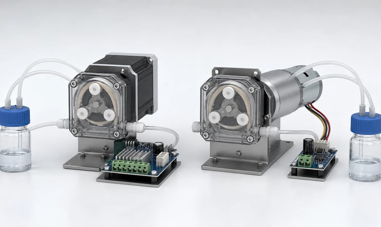
Stepper and DC motor peristaltic pumps differ in how they command position and speed, start at low flow, respond to changing tube and pressure load, generate heat and noise, use feedback, recover from stalls, and support dosing or continuous-flow requirements.
Stepper Motor vs DC Motor Peristaltic Pumps
Stepper and DC motors can both drive peristaltic pumps, but they support different control strategies. A stepper motor advances through commanded increments, making rotor position and cycle counting straightforward when no steps are lost. A DC motor rotates continuously in response to voltage, PWM, or an electronic speed command and may use feedback to regulate speed or position.
Motor type alone does not determine dosing accuracy. Tubing dimensions, tube recovery, occlusion, roller geometry, inlet refill, outlet pressure, fluid properties, gearbox behavior, calibration, and control timing also affect delivered volume.
The best choice depends on whether the application prioritizes short discrete doses, wide continuous-flow range, quiet operation, power efficiency, simple electronics, fast priming, position control, or fault detection.
Define the Pumping Task First
Start with the fluid and process requirements rather than a preferred motor technology.
Document:
Minimum, typical, and maximum flow
Minimum and maximum dose volume
Allowed dose variation
Time available for each dose
Continuous, intermittent, or mixed duty
Prime and purge flow
Inlet vacuum and outlet pressure
Fluid viscosity and temperature range
Starts, stops, reversals, and suck-back moves
Noise, heat, size, power, and cost limits
Control interface and feedback needs
Expected tubing replacement and calibration process
A small dose may favor controlled rotor movement, but only if the trapped volume and tube behavior are repeatable enough. A continuous-flow application may favor efficient rotation over a wide speed range, but it still needs stable speed under changing load.
Calculate active flow from dose volume divided by the available dispense time. Selecting a pump only from average daily volume can lead to a motor and tube size that cannot meet the real cycle.
How a Stepper Peristaltic Pump Works
A stepper motor moves its rotor in discrete electrical steps. A driver energizes winding phases in sequence, and microstepping can command intermediate current positions between full steps.
The pump controller can issue a defined number of steps for a dose or a defined step frequency for continuous rotation. When the motor follows every command, commanded position is known without a separate encoder.
Potential advantages include:
Straightforward incremental position control
Repeatable start and stop positions
Easy counting of complete or partial pump revolutions
Useful low-speed control with a suitable driver and load
Defined direction and reversal commands
Holding torque when energized
Potential limitations include:
Lost steps may go undetected in open loop
High holding or low-speed current can create heat
Torque decreases as speed rises
Resonance can cause noise, vibration, or missed motion
Microsteps are not always equal mechanical increments under load
Driver electronics and current tuning are required
The motor may be direct drive or use a gearbox. Gear reduction changes torque, resolution, speed, backlash, noise, and efficiency.
How a DC Motor Peristaltic Pump Works
A DC motor produces continuous rotation. Brushed DC motors use mechanical commutation, while brushless DC motors use electronic commutation. Either may drive the pump directly or through a gearbox.
An open-loop brushed pump can use applied voltage or PWM as a speed command. A brushless pump may accept PWM, analog, frequency, or digital commands through an integrated driver. Speed feedback from a Hall sensor, encoder, tachometer, or internal electronics can support closed-loop regulation.
Potential advantages include:
Smooth continuous rotation in a suitable operating range
High prime or purge speed in many configurations
Potentially efficient operation, especially with a matched brushless system
Simple external control for some brushed pumps
Wide availability of compact motors and gear ratios
Potential limitations include:
Open-loop speed changes with voltage, load, and temperature
Rotor position is unknown without feedback
Very low speed may be unstable in some configurations
Gearbox backlash and motor coast affect short moves
Brushed motors introduce brush wear and electrical noise
Brushless motors require commutation electronics
"DC pump" is not one uniform category. Compare the specific motor, gearbox, driver, feedback, and pump head.
Compare Dose Resolution
Command resolution is not the same as fluid resolution. A stepper driver can command many increments per revolution, but the smallest reliably delivered liquid change may be much larger.
Fluid resolution is limited by:
Volume displaced between roller events
Tube inner diameter and wall dimensions
Roller count and track geometry
Elastic deformation and pressure storage
Tube recovery and inlet refill
Backlash or rotor movement before fluid output
Bubbles and compressible volume
Nozzle wetting and drop formation
Measurement resolution
A stepper pump makes it easier to command repeatable angular movement. This can improve short-dose control when the pump has enough torque and the fluid path responds consistently.
A DC pump with an encoder or other position feedback can also count revolutions or partial turns. An open-loop timed DC command generally provides less direct knowledge of rotor position, particularly during acceleration and stopping.
Test actual individual doses. Do not calculate minimum dose only by multiplying theoretical volume per revolution by microstep angle.
Compare Dosing Accuracy and Repeatability
Accuracy describes closeness to the target. Repeatability describes the spread between repeated doses. A motor choice can influence both, but tubing and fluid conditions often dominate long-term results.
Stepper control can deliver a repeatable number of commanded steps and park at a defined rotor position. However, lost steps, insufficient torque, microstep nonlinearity, tube wear, and pressure still change fluid output.
A closed-loop DC pump can regulate actual speed or count encoder pulses. A timed open-loop DC pump may vary more with supply voltage, friction, load, and temperature.
For either type, evaluate:
First dose after idle
Minimum and maximum dose
Acceleration and deceleration
Complete and partial rotor cycles
New and aged tubing
Minimum and maximum outlet pressure
Cold and warm fluid
Full and low reservoir level
Prime, dispense, reverse, and valve timing
Calibration can correct average scale error under defined conditions. It cannot remove random bubbles, lost motion, incomplete tube refill, or changing tube condition.
Compare Low-Speed Performance
Stepper motors are often selected for low flow because step frequency can be reduced while retaining commanded incremental motion. Performance still depends on available torque, resonance, driver current, microstepping, and pump-load variation.
At very low speed, peristaltic flow remains cyclic. Long pauses between roller events can create visibly intermittent delivery even when average flow is low and controlled.
A DC motor may have a minimum reliable startup or running speed. Brushed contact variation, gearbox friction, brush voltage drop, sensorless brushless commutation, and limited feedback resolution can affect low-speed smoothness.
Closed-loop DC control can improve speed regulation, but aggressive control may react to cyclic roller load and create speed modulation.
Compare actual flow waveform, average flow, startup, stall margin, acoustic behavior, and heat at the minimum required operating point. Do not compare only controller command range.
Compare High-Speed and Priming Performance
Prime and purge modes may require much higher speed than dosing. Stepper torque normally falls as step rate rises because winding current has less time to change. Driver voltage, inductance, motor size, load inertia, acceleration, and resonance affect the usable maximum speed.
DC motors often provide a broad continuous-rotation range and may suit fast priming, but performance depends on gearbox, driver, supply voltage, and pump load.
The pump head and fluid path can become the limit before the motor. At high speed, peristaltic tubing may not reopen and refill completely, especially with viscous fluid or inlet restriction. Increasing speed can then produce little additional flow.
Test maximum useful flow, not merely maximum rotor speed. Record inlet vacuum, outlet pressure, current, tube recovery, flow, and temperature.
Use a controlled acceleration profile. An abrupt start can miss stepper motion, create pressure spikes, draw excessive current, or increase bubbles.
Compare Torque and Load Margin
Peristaltic pumps have a cyclic torque load as rollers enter, travel through, and leave the compression track. Tube hardness, wall thickness, occlusion, temperature, wear, outlet pressure, and pump-head tolerances change the required torque.
Stepper motors can provide high holding and low-speed torque, but available torque decreases with speed. Open-loop operation requires enough margin to avoid missed steps during the worst part of the cycle.
DC motor speed decreases as load rises unless the controller compensates. Current usually increases with torque, so current limiting, voltage droop, driver heat, and gearbox capability matter.
Verify torque margin using:
Cold and hottest approved tube conditions
New and representative aged tubing
Maximum approved occlusion
Maximum outlet pressure
Minimum supply voltage
High-viscosity or cold fluid
Startup after long idle
Acceleration, reversal, and blockage
Do not compensate for insufficient torque by increasing tube compression or current beyond approved limits.
Compare Position Control and Rotor Parking
Known rotor position can support complete-cycle dosing, repeatable start position, controlled shutoff, and anti-siphon strategies.
A stepper pump can track commanded position in open loop if it never loses steps. A home sensor, index sensor, or encoder can establish reference and detect position errors.
A DC pump requires position feedback when exact angular stop is needed. A simple speed signal may count revolutions but provide insufficient resolution for a precise parking point. Motor coast, gearbox backlash, and braking affect final position.
For either system, verify:
Power-up position knowledge
Homing behavior
Position error after stall or manual movement
Stop accuracy under pressure
Motion during power loss
Gear backlash
Recovery after communication or sensor fault
Software position cannot guarantee fluid shutoff if tube occlusion, head closure, or tubing condition is inadequate. Use a separate valve when the application requires an independent barrier.
Compare Heat and Power Consumption
Stepper motors can consume substantial power while holding position or running slowly because the driver maintains winding current. Current reduction during idle can lower heat, but it also reduces holding torque.
DC motor input generally changes with speed and torque. Brushed motors have brush and winding losses. Brushless systems add driver switching and conduction losses but may achieve higher efficiency in a matched operating range.
Measure system input and temperature rather than relying on motor type:
Supply voltage and current
Motor and driver temperature
Gearbox and pump-head temperature
Enclosure-air and fluid temperature
Duty cycle and idle current
Flow and pressure at the test point
Heat can change tubing flexibility, fluid viscosity, valve behavior, electronics, and calibration. Test in the closed production enclosure until temperatures reach a defined steady condition.
Compare Noise and Vibration
Stepper systems can produce tonal noise and resonance from discrete torque excitation, microstepping, driver current regulation, gears, and the peristaltic load. The sound may be particularly noticeable at certain step rates.
DC systems may produce brush, commutation, PWM, gear, and speed-control noise. Brushless does not automatically mean silent, and brushed does not automatically mean unacceptable.
The pump head, mounting, tubing, pressure pulsation, and enclosure can dominate both choices.
Perform speed sweeps at equal delivered flow and pressure. Record acoustic and vibration spectra, pump speed, current, tube condition, and temperature. Check startup, priming, dosing, reversal, and shutdown.
Changing microstep mode, PWM frequency, driver decay mode, current, or control gains can alter sound but may also affect torque, heat, electromagnetic compatibility, and position accuracy.
Compare Electronics and Software
A stepper pump requires a current-controlled driver and step or motion-generation logic. The controller must manage step frequency, acceleration, direction, current, and fault states.
A basic brushed DC pump may use a transistor or H-bridge with PWM. A brushless pump requires commutation, which may be integrated into the pump. Feedback adds sensor inputs and control logic.
Compare the complete interface:
Power rails and peak current
Step/direction, PWM, analog, frequency, or digital command
Speed or position feedback
Driver enable and safe startup state
Stall, overcurrent, and overtemperature detection
Communication loss and watchdog behavior
Calibration storage and integrity
Firmware update and configuration control
Stepper motion commands may be deterministic, but a blocked rotor can lose steps silently without feedback. DC current can indicate load but cannot by itself prove flow or position.
Define how the system detects failed motion and moves to a safe state.
Compare Fault Detection and Recovery
Fault behavior should be designed before motor selection is finalized.
For an open-loop stepper, possible faults include lost steps, resonance stall, insufficient startup torque, disconnected winding, and driver thermal shutdown. Position may remain wrong after the motor begins moving again.
For a DC system, possible faults include stalled rotor, worn brushes, commutation failure, encoder loss, driver current limiting, gearbox damage, and speed-control error.
Test both motor options under:
Blocked pump head
Blocked inlet and outlet
Excessive tube load
Minimum supply voltage
Cold startup
Failed or disconnected feedback
Communication interruption
Immediate power loss
Repeated reset or retry
Record detection method, detection time, current, temperature, delivered volume during the fault, and recovery state. Avoid unlimited automatic retries that create heat or an unexpected dose after the obstruction clears.
Consider Calibration and Tube Replacement
Motor position or speed is only one input to peristaltic calibration. Tube dimensions, elasticity, run-in, wear, pressure, fluid viscosity, temperature, and inlet refill determine volume per revolution.
Define:
Calibration fluid and temperature
Speed or motion profile
Outlet pressure
Tube part number and condition
Number and size of calibration doses
Measurement method
Coefficient limits and storage
Recalibration trigger
A step-count calibration can be intuitive because output is linked to commanded motion. A closed-loop DC pump can similarly calibrate volume per encoder count or revolution. A timed open-loop DC pump typically calibrates volume per unit time at a defined command.
After tube replacement, verify installation, occlusion, prime, flow, dose, leakage, and calibration. Do not assume motor repeatability removes tube-to-tube variation.
Compare Cost at the System Level
Include more than the pump purchase price.
Stepper system cost may include:
Current-controlled driver
Higher peak or holding power provision
Motion-control firmware
Heat management
Optional home or position sensor
Acoustic tuning
DC system cost may include:
H-bridge or brushless driver
Speed or position feedback
Closed-loop firmware
Electromagnetic filtering
Braking or reversal control
Brush service exposure or integrated-electronics cost
Both require tubing, mechanical integration, testing, calibration, fault handling, and production controls.
Choose based on total product cost and risk. A more expensive closed-loop pump may reduce software or calibration uncertainty, while a simpler motor may be sufficient for a tolerant transfer function.
Validate the Final Pump System
Bench comparisons should use equal requirements, not equal motor commands. Compare delivered flow, pressure, dose, heat, noise, and power in the final fluid path.
Test:
Minimum and maximum flow or dose
Prime and purge speed
Minimum and maximum pressure
Fluid viscosity and temperature range
New, run-in, and aged tubing
Minimum and maximum supply voltage
Cold startup and thermal steady state
Stops, starts, reversals, and idle holding
Speed or position feedback failure
Blockage, empty source, and air ingestion
Production motor, driver, gearbox, and tube variation
Use the final enclosure, mounting, cable routing, electronics, and firmware. Record raw command, speed or position, current, pressure, flow, temperature, and dose data.
The selected pump should meet requirements with margin without depending on unverified tube compression, unsupported current, or ideal laboratory conditions.
Selection Checklist
Flow, dose, timing, pressure, and fluid requirements defined
Continuous, intermittent, prime, purge, and reversal modes documented
Minimum fluid resolution measured rather than calculated from motor steps
Low-speed startup and stable operation verified
Maximum useful speed checked for complete tube refill
Torque margin tested at pressure, voltage, and temperature extremes
Position knowledge, homing, parking, and power-loss behavior defined
Lost-step or speed-error detection evaluated
Motor, driver, gearbox, pump-head, and enclosure heat measured
Noise and resonance mapped across the operating range
Power, driver, feedback, and firmware requirements included
Calibration and tube-replacement process validated
Blockage, communication, feedback, and retry faults tested
Multiple production-representative samples evaluated
System-level cost and service exposure compared
Common Selection Mistakes
Assuming microstep count equals liquid-dose resolution
Assuming every DC pump is open loop
Comparing command range instead of delivered flow range
Ignoring stepper torque loss at higher speed
Ignoring DC motor behavior at very low speed
Using holding current without checking enclosure heat
Selecting from motor torque without the cyclic tube load
Treating rotor position as proof of fluid delivery
Comparing pumps at different outlet pressure
Ignoring tube wear, run-in, and replacement calibration
Changing driver settings without checking torque, noise, heat, and EMC
Adding feedback without defining fault recovery
Testing only nominal voltage and room-temperature water
Comparing motor price instead of total system cost
Frequently Asked Questions
Is a stepper peristaltic pump more accurate than a DC pump?
Not automatically. A stepper simplifies commanded position, but dosing also depends on tubing, pressure, refill, bubbles, calibration, and lost steps. A closed-loop DC pump can also provide accurate motion control.
Are microsteps equal to equal liquid volumes?
No. Microsteps command winding-current positions, and mechanical motion under load may not divide evenly. Fluid output is further affected by roller geometry, tubing elasticity, pressure, and nozzle behavior.
Which motor is better for very low flow?
A stepper can support controlled low-speed increments, while a feedback-controlled DC system may also work well. Compare minimum stable fluid output, pulsation, heat, torque, and dose requirements in the actual system.
Which pump is better for fast priming?
DC motors often support broad continuous speed, while stepper maximum speed depends on available torque and driver design. In both cases, tube refill and inlet resistance may limit useful prime flow.
Does a stepper pump need an encoder?
Not always, but an encoder or home sensor can establish reference and detect lost motion when position errors are unacceptable. Open-loop step counting assumes the rotor follows every command.
How should an OEM compare stepper and DC peristaltic pumps?
Test both at the same flow, pressure, fluid, temperature, voltage, duty, tubing condition, and enclosure configuration while measuring dose, speed, current, heat, noise, and faults.
Kamoer Peristaltic Drive Selection Support
Kamoer can help compare stepper, brushed DC, and brushless DC peristaltic pump configurations using dose, flow, speed, pressure, tube load, control, feedback, heat, noise, calibration, and OEM integration requirements.
Related Stories
Kamoer Fluid Tech (Shanghai) Co., Ltd.
pump@kamoer.com