

Peristaltic Pumps for Laboratory Electrolysis Systems
APPLICATIONSLABORATORY AUTOMATION
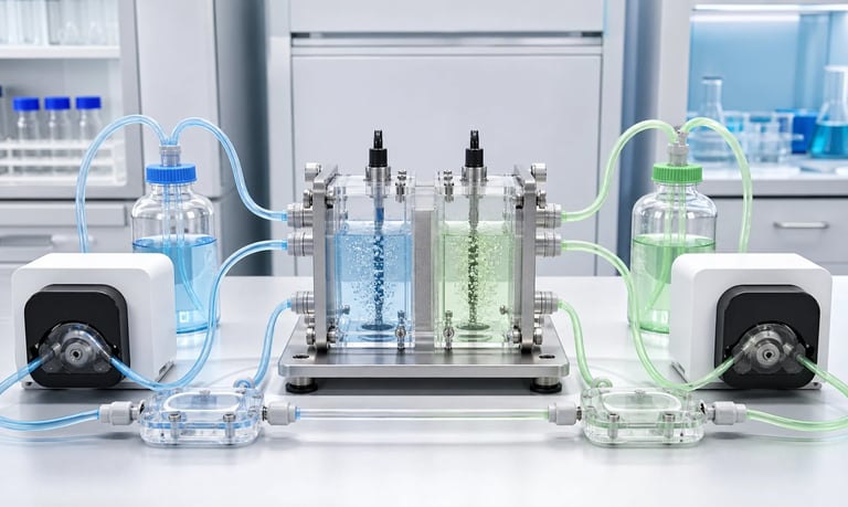
Stable laboratory electrolysis circulation depends on a peristaltic pump matched to electrolyte chemistry, target flow, gas bubbles, tubing compatibility, pressure loss, temperature, control, maintenance, and experimental safety.
Peristaltic Pumps for Laboratory Electrolysis Systems
Laboratory electrolysis systems may use peristaltic pumps to circulate electrolyte, feed reactants, transfer samples, rinse cells, and control liquid residence time. Because the liquid remains inside the tubing, the pump head can be isolated from corrosive or contamination-sensitive fluids.
That advantage does not make every peristaltic pump or tube suitable for every electrolyte. Chemical concentration, temperature, gas generation, solids, pressure, flow stability, and tubing fatigue must be evaluated for the actual experiment.
Define the Fluid-Circulation Function
The pump may provide:
Continuous electrolyte circulation
Metered reactant addition
Separate anolyte and catholyte loops
Sampling and return flow
Cell filling and drainage
Rinsing between experiments
Fluid transfer through sensors or heat exchangers
Define minimum, typical, and maximum flow, run duration, required direction, and whether channels must be synchronized.
Why Peristaltic Pumps Are Considered
The electrolyte contacts only the pump tubing and external fluid-path components. This can simplify material selection, fluid-path replacement, cleaning, and separation between circuits.
Flow can be controlled by tube size, speed, and run time. Reversible operation may support filling, draining, or purging.
Limitations include flow pulsation, tubing wear, pressure limits, flow drift, and the need to validate tubing against the electrolyte.
Evaluate Electrolyte Compatibility
Provide the exact chemical composition, concentration, temperature, pH, solvents, salts, additives, and cleaning agents. Include products that may form during electrolysis.
Compatibility should be verified under actual concentration, temperature, pressure, electrical experiment duration, and idle exposure. A tube may appear resistant in a short immersion test but lose elasticity or fatigue resistance during repeated compression.
Inspect for swelling, hardening, cracking, discoloration, permeation, mass change, and loss of recovery.
Manage Gas Bubbles
Electrolysis generates gas at electrode surfaces. Bubbles may enter the circulating liquid and affect flow, sensor readings, heat transfer, pressure, and dose calculations.
Possible controls include:
Gas-liquid separators
Reservoir geometry that allows bubbles to escape
Vertical routing near separation points
Lower pump speed where appropriate
Bubble detection
Avoiding inlet locations near active gas release
Test with the real gas-generation rate. Water circulation without electrolysis may not reproduce bubble behavior.
Select the Flow Range
Flow influences mass transport, residence time, temperature uniformity, electrode conditions, and gas removal. Excessive flow may disturb the experiment or increase pressure; insufficient flow may create concentration and temperature gradients.
Calculate the required range from cell volume and experimental objectives, then select tubing and speed that keep normal operation away from pump extremes.
Calibrate with the actual electrolyte, tubing, pressure, temperature, and gas conditions.
Account for Pressure Loss
Electrochemical cells may include narrow channels, membranes, porous electrodes, sensors, valves, heat exchangers, and filters. These components create back pressure.
Higher pressure can reduce flow, stress tubing and fittings, increase motor load, and change leakage risk. Measure pressure in the assembled loop and include deposits or filter loading expected during the experiment.
Control Pulsation
Roller compression creates periodic flow variation. Pulsation may influence sensitive pressure measurements, membrane loading, gas movement, and flow-through sensors.
Possible measures include lower speed, more suitable pump-head geometry, flexible outlet tubing, a compatible pulsation damper, or multiple channels operated out of phase.
Verify that any damper or accumulator is chemically compatible and does not add unacceptable dead volume.
Separate Anolyte and Catholyte Loops
Some cells require independent circulation paths to prevent mixing. Use separate tubing and pump channels where cross-contamination is unacceptable.
Confirm that channel flow rates remain balanced if membrane pressure difference matters. Separate calibration, flow sensing, or feedback may be required.
Consider Temperature
Electrolysis and electrical resistance can heat the fluid. Temperature changes viscosity, reaction rate, tube flexibility, chemical compatibility, and delivered flow.
Place temperature measurement where it represents the circulating electrolyte. If a heat exchanger is used, include its pressure loss in pump testing.
Design Safe Fluid Routing
Use fittings compatible with the tube and electrolyte.
Keep liquids away from exposed electrical connections.
Provide secondary containment and leak detection where appropriate.
Avoid sharp bends and tube tension.
Vent generated gases safely according to the experiment.
Consider chemical hazards, pressure, flammability, and gas accumulation.
Pump selection does not replace laboratory risk assessment or appropriate controls for the electrochemical process.
Plan Maintenance and Calibration
Tubing is a consumable. Establish a replacement interval from representative tests using the actual speed, electrolyte, pressure, temperature, and duty cycle.
Record tube batch, run hours, flow drift, pressure, temperature, and visible condition. Recalibrate after tube replacement and inspect rollers, tracks, fittings, and containment.
Validation Checklist
Exact electrolyte and cleaning fluids
Minimum and maximum flow
Gas-generation conditions
Temperature range
Cell, membrane, filter, and heat-exchanger pressure loss
Pulsation at sensors and cell inlet
Tube life and chemical change
Start, stop, reverse, drain, and restart
Leak and blocked-line faults
Balanced flow in separate loops
Frequently Asked Questions
Can a peristaltic pump handle corrosive electrolyte?
It may be possible when the tubing and external wetted components are compatible. Verify the exact chemistry and operating conditions through testing.
Do gas bubbles damage the pump?
The pump can move air-liquid mixtures in some conditions, but bubbles may reduce flow stability and measurement accuracy. Large gas volumes can disrupt circulation.
How should flow be calibrated?
Use the actual electrolyte, tube, temperature, pressure, and representative gas conditions. Measure multiple runs and recalibrate after tube replacement.
Can one pump drive two electrolyte loops?
A multichannel pump may do so, but channel balance, tube tolerances, pressure differences, and cross-contamination requirements must be evaluated.
Does tubing affect experimental results?
Yes. Adsorption, permeation, extractables, chemical change, and flow drift can influence sensitive experiments. Validate the complete fluid path.
Kamoer Laboratory Pump Support
Kamoer can help evaluate electrolyte compatibility, tubing, flow, pressure, gas bubbles, control, temperature, duty cycle, and multichannel requirements for laboratory electrolysis systems.
Related Stories
Kamoer Fluid Tech (Shanghai) Co., Ltd.
pump@kamoer.com