

OEM Micro Pump Testing Checklist Before Production
MICRO PUMP BASICS
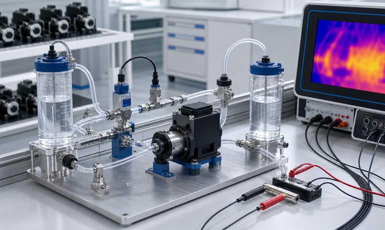
An OEM micro pump should be verified in the final fluid path, enclosure, control system, fluid, environmental range, duty cycle, cleaning process, and foreseeable fault conditions before production approval, with measurable acceptance criteria and traceable test records.
OEM Micro Pump Testing Checklist Before Production
A micro pump that works on an open bench may behave differently after it is installed in an OEM product. Production tubing, fittings, valves, filters, software, power supply, enclosure temperature, fluid properties, and mounting can change flow, pressure, priming, noise, heat, and service life.
Pre-production testing should therefore verify the complete pumping function, not only the pump as a separate component. The test plan must define measurable requirements, representative samples, operating extremes, fault conditions, and clear acceptance criteria before testing begins.
This checklist provides a framework for OEM teams. The actual scope, sample quantity, duration, and acceptance limits should be based on application risk, product requirements, applicable standards, supplier data, and the consequences of failure.
Freeze the Test Configuration
Testing is meaningful only when the configuration is controlled. Record the hardware and software used for every result.
Identify:
Pump model, revision, serial or lot identification
Motor, gearbox, pump head, tubing, diaphragm, valves, and seals
Driver electronics and firmware version
Power supply, cables, connectors, and protection devices
Reservoir, pickup, tubing, fittings, filters, sensors, valves, and nozzle
Mounting bracket, fasteners, isolation parts, and enclosure
Fluid identity, concentration, lot, preparation, and age
Cleaning, priming, calibration, and operating procedures
Test equipment model, calibration status, range, and sample rate
If the configuration changes during testing, document the change and determine which results must be repeated. Do not combine data from different revisions without identifying the differences.
The final production routing matters. Small changes in tube length, internal diameter, fitting bore, elevation, or clamp position can alter the load on a micro pump.
Convert Product Needs into Acceptance Criteria
Write acceptance criteria before collecting data. Terms such as "quiet," "accurate," "self-priming," or "continuous duty" are not sufficient by themselves.
Define requirements for relevant operating modes:
Minimum, typical, and maximum flow
Dose volume and repeatability
Inlet vacuum and outlet pressure
Prime time and maximum allowed retries
Startup and shutdown response
Maximum current, power, and temperature
Noise and vibration at defined locations
Allowed leakage, backflow, or post-stop dripping
Service interval or validated operating exposure
Fault detection and safe response
State the fluid, temperature, pressure, voltage, tubing condition, reservoir level, and measurement method attached to each limit. A flow requirement without these conditions can be interpreted in several incompatible ways.
Separate average performance from individual-unit limits. If statistical capability is required, define the analysis method, sample plan, and tolerance basis with the responsible quality team.
Select Representative Test Samples
One hand-selected prototype cannot demonstrate production consistency. Include variation that is likely to affect performance.
Consider samples from:
More than one pump or component lot
Minimum and maximum relevant dimensional conditions
Different tubing or consumable lots
Different production assembly operators or stations
Minimum and maximum supply conditions
New and representative aged components
Expected fluid lots or formulation limits
Use a risk-based sample plan. Higher-risk functions, destructive tests, long-duration testing, and production capability studies may need different sample quantities.
Do not repeatedly tune every sample to pass unless that adjustment is part of the controlled production process. Record any calibration, occlusion setting, screw torque, valve setup, or software coefficient applied to each unit.
Verify Flow Across the Operating Range
Measure delivered flow in the final fluid path, not only at an open pump outlet. Test the complete command range and the conditions that create the highest and lowest system resistance.
Include:
Minimum, nominal, and maximum pump command
Minimum and maximum fluid temperature
Minimum, typical, and maximum viscosity
Full and low source-reservoir level
Minimum and maximum outlet pressure
Clean and realistically loaded filters
Minimum and maximum supply voltage
New and aged tubing, diaphragms, or valves
Record both commanded speed and actual flow. Check whether the speed-to-flow relationship remains usable across the range. Incomplete inlet refill, valve delay, leakage, tubing wear, or high pressure can make flow nonlinear.
Where flow is measured gravimetrically, use verified fluid density to convert mass to volume if volume is the required result. Control evaporation and confirm that the collection interval is long enough for the required resolution.
Verify Dosing Accuracy and Repeatability
Average flow testing does not establish the performance of short, discrete doses. Test the actual dispense sequence, including acceleration, deceleration, valve timing, and any pressure release or suck-back step.
Measure:
Individual dose mass or volume
Mean, spread, and drift over repeated doses
First dose after startup or long idle
Minimum and maximum dose size
Different pump speeds or dispense profiles
Reservoir-level and outlet-pressure extremes
Fluid temperature and viscosity extremes
New and aged fluid-path components
Do not discard the first dose unless the production process also includes a defined purge or discard. Include realistic delays between doses because tubing recovery, pressure relaxation, evaporation, settling, and fluid structure may change during idle.
If calibration is used, define how it is created, stored, checked, and updated. Confirm that a failed, missing, or corrupted coefficient produces a safe and detectable result.
Test Priming, Restart, and Dry Conditions
Priming must be evaluated from the states the user or equipment may actually encounter.
Test:
Completely dry pump and inlet path
Partially filled or drained path
Empty line after cleaning
Low reservoir level
Maximum suction lift or inlet restriction
Cold and high-viscosity fluid
Wet restart after short and long idle
Restart against residual outlet pressure
Reversed flow where the design uses it
Record prime time, delivered air and liquid behavior, current, pressure, and the number of allowed attempts. Confirm that software timeouts do not stop a valid cold prime too early or allow an empty pump to run indefinitely.
Peristaltic pumps can often tolerate dry running better than pumps with fluid-lubricated or fluid-cooled internal parts, but the acceptable duration still depends on the exact pump, tube, speed, pressure, and temperature. Validate the intended dry-run behavior rather than applying a general assumption.
Measure Inlet Vacuum and Outlet Pressure
Flow alone may hide a system operating near its limit. Instrument the inlet and outlet close to the pump while preserving representative line geometry.
Evaluate inlet vacuum with the lowest reservoir level, coldest or most viscous fluid, longest inlet routing, and loaded inlet filter. Check for soft-tube collapse and air entry through fittings.
Evaluate outlet pressure with the full production path, maximum elevation, smallest nozzle, loaded filter, and all valves or sensors installed. Capture transient peaks during startup, valve switching, and shutdown, not only steady pressure.
The sensor must have adequate range and response speed. Its ports and internal volume should not materially change the fluid path. Record whether reported pressure is gauge, absolute, differential, or vacuum so that results are interpreted correctly.
Validate Fluid and Material Compatibility
Review every wetted material, including pump tubing, diaphragms, valves, seals, fittings, adhesives, lubricants, reservoir parts, and sensors. The production fluid is only one exposure.
Also test or assess:
Cleaning and sanitizing agents
Rinse fluid and mixed waste
Concentration limits and fluid impurities
Minimum and maximum temperature
Continuous exposure and long idle while filled
Repeated wet-dry or thermal cycles
Mechanical compression, flexing, and pressure
Static immersion data can support screening but may not represent cyclic pumping. Inspect for swelling, softening, hardening, cracking, discoloration, tackiness, mass change, leakage, valve sticking, loss of tube recovery, and flow drift.
Do not make universal chemical, food-contact, medical, or regulatory claims from material-family names alone. Confirm the exact grade and approved documentation for the intended market and process.
Verify Temperature and Thermal Stability
Measure the system until temperature stabilizes in the final enclosure. Short open-bench tests can miss heat accumulation from the motor, driver, pump head, nearby electronics, heaters, and restricted ventilation.
Record:
Ambient and enclosure-air temperature
Fluid inlet and outlet temperature
Motor, driver, pump head, and critical tubing temperature
Current, speed, flow, and pressure during warm-up
Time to reach a defined steady condition
Test cold startup, maximum ambient operation, repeated intermittent cycles, and continuous or longest permitted run. Include minimum and maximum supply voltage where it affects current and heat.
Confirm that thermal protection, duty-cycle limits, or software derating respond safely. If cooling or ventilation is required, test blocked vents, fan faults, filter loading, and realistic dust accumulation as appropriate to the product design.
Test Electrical and Control Behavior
The pump and driver must function together across normal and abnormal electrical conditions. Evaluate the exact production electronics and wiring.
Depending on the design, test:
Minimum and maximum supply voltage
Startup current and supply droop
Current limit and stall response
PWM frequency and duty range
Analog-command tolerance and noise
Digital communication loss or invalid commands
Motor speed feedback and sensor plausibility
Connector interruption and intermittent contact
Power cycling and brownout recovery
Reverse polarity or misconnection protection where designed
Electromagnetic compatibility under the applicable product plan
Verify that the pump does not start unexpectedly during boot, firmware update, communication recovery, or fault reset. Confirm the safe state for a stuck command, frozen software task, failed sensor, and corrupted calibration value.
Log the commanded state and actual response with sufficient time resolution to diagnose intermittent events.
Evaluate Noise and Vibration in the Product
Pump noise can be transmitted through mounting points, tubing, panels, and the product structure. A pump that sounds acceptable when held in free air may excite an enclosure resonance after installation.
Test in the final mechanical assembly at relevant speeds, pressures, temperatures, and reservoir levels. Record the microphone or vibration-sensor position, mounting, background level, and measurement method.
Look for:
Structural resonance at specific speeds
Tube or fitting contact with panels
Valve clicking and pressure ripple
Gear, bearing, or roller noise
Changes after warm-up or component aging
Noise during priming, bubbles, blockage, and dry running
Isolation mounts can reduce transmitted vibration but may allow movement that strains tubing or connectors. Confirm fastener retention and fluid-path clearance through environmental and life testing.
Check Leakage, Backflow, and Shutoff
Inspect every fluid connection under maximum pressure, vacuum, temperature, and mechanical load. Include fittings that may not leak liquid outward but can draw air inward on the suction side.
Verify:
External leakage during operation and idle
Backflow through the pump or valves
Siphoning with relevant reservoir and outlet elevations
Dripping or stored-volume release after stop
Fitting retention under pull, vibration, and thermal cycling
Drainage and residual fluid after cleaning
Use a defined detection method and observation time. Visual inspection alone may not detect small leaks, air ingress, or slow backflow.
If a separate shutoff valve is required, test its timing relative to the pump and its behavior after contamination, aging, and power loss.
Run Duty-Cycle and Life Tests
Life testing should reproduce the damaging mechanisms expected in use, not merely accumulate motor hours. Define speed, pressure, fluid, temperature, starts, stops, reversals, idle periods, cleaning cycles, and environmental exposure.
Track performance throughout the test rather than inspecting only at the end:
Flow or dose drift
Prime time
Inlet vacuum and outlet pressure
Current, speed, and temperature
Noise and vibration
Leakage and backflow
Tube, diaphragm, valve, seal, gear, and bearing condition
Particle generation or fluid contamination where relevant
Use periodic checkpoints with consistent test conditions so trends can be compared. Record maintenance and consumable replacement. A test with frequent unplanned adjustments does not represent unattended field operation unless those adjustments become defined service steps.
Accelerated testing requires evidence that the increased stress produces the same relevant failure mechanisms as normal use. Excessive speed, temperature, pressure, or chemical concentration can create unrealistic failures or hide time-dependent behavior.
Test Cleaning, Maintenance, and Consumable Replacement
Validate the production cleaning sequence with the actual geometry, product residue, cleaner, concentration, temperature, contact time, flow direction, rinse, and drain process.
Confirm:
Residue is removed from low-flow and dead-volume regions
The cleaner reaches all required surfaces
Valves and filters do not trap product
The system drains or remains filled as intended
Cleaning does not create incompatible mixed fluids
Calibration remains valid or is restored afterward
The number of permitted cleaning cycles is defined
Evaluate replacement of tubing, pump heads, diaphragms, valves, filters, or complete pump modules. Check access, connector keying, tube routing, clamp position, torque, leak testing, calibration, and service instructions.
A replacement procedure should not depend on hidden expertise that will be unavailable on the production line or in the field.
Test Foreseeable Fault Conditions
Fault testing verifies that the system detects problems and moves to a safe state without creating a larger hazard or uncontrolled dose.
Consider:
Empty source reservoir
Blocked inlet or outlet
Kinked or disconnected tubing
Inlet air leak
Pump stall or locked rotor
Worn or ruptured peristaltic tube
Diaphragm, valve, or seal failure
Failed flow, pressure, temperature, or level sensor
Incorrect pump installation or tubing direction
Communication loss or invalid command
Interrupted power and unexpected restart
Maximum run-time or repeated-prime timeout
For each fault, document detection method, detection time, system response, user indication, stored diagnostic data, and recovery procedure.
Motor current alone may not distinguish blockage, high viscosity, cold fluid, excessive occlusion, mechanical wear, or low voltage. Combine signals when the risk requires more reliable diagnosis.
Include Environmental and Transport Conditions
The product environment can affect the pump before and during operation. Select tests from the actual use, storage, and shipment profile.
Potential conditions include:
Low and high operating temperature
Storage temperature and recovery time
Humidity and condensation
Altitude or reduced ambient pressure
Dust, splash, cleaning, or chemical vapor
Mechanical shock and vibration
Transport orientation and long storage
Repeated thermal cycling
Inspect fluid connections, mounting, wiring, calibration, prime behavior, and leakage after exposure. Test with filled and empty fluid paths where both states may occur.
Applicable environmental, safety, and electromagnetic tests depend on the final product and market. Coordinate them with the responsible compliance team rather than assuming component-level evidence covers the complete OEM equipment.
Prepare Production Controls
Design verification does not ensure every production unit is assembled correctly. Translate critical characteristics into supplier controls, incoming inspection, assembly instructions, end-of-line tests, and traceability.
Define:
Critical pump and fluid-path part numbers and revisions
Approved suppliers and change-notification requirements
Tubing cut length, insertion depth, clamp position, and routing
Fastener torque and mounting sequence
Electrical polarity, connector seating, and cable routing
Calibration equipment and coefficient limits
End-of-line flow, pressure, current, leak, or prime checks
Test-fluid control, drainage, drying, and contamination prevention
Nonconformance handling and retest rules
Serial or lot data retained for traceability
End-of-line tests should be fast enough for production but sensitive to meaningful assembly faults. Correlate them with the more complete engineering tests used during validation.
Review Supplier Changes and Second Sources
A change in pump revision, motor, magnet, gear, lubricant, tube formulation, diaphragm, valve material, electronics, or manufacturing process can affect system performance even when the external dimensions remain unchanged.
Agree on change communication and define which changes trigger document review, sample testing, partial requalification, or full revalidation.
Second-source components should be tested as separate configurations. Similar dimensions or material descriptions do not prove equivalent flow, pressure, recovery, noise, chemical response, or life.
Keep approved drawings, specifications, supplier reports, deviation records, and validation results connected to the production bill of materials.
Build a Traceable Test Report
The report should allow another engineer to understand and repeat the work. Include:
Requirement and acceptance criterion
Test method and equipment
Configuration and sample identification
Environmental and fluid conditions
Raw data location and processing method
Results, deviations, failures, and retests
Photos or diagrams of the setup
Firmware, calibration, and analysis versions
Conclusions, limitations, and open risks
Reviewer and approval records
Do not report only pass or fail. Retain enough raw information to investigate later changes and field issues.
Document any condition that was not tested. An explicit limitation is more useful than an unsupported assumption that the result applies everywhere.
Pre-Production Micro Pump Checklist
Pump, consumable, electronics, software, and fluid-path revisions frozen
Test samples represent relevant production variation
Requirements and acceptance criteria approved before testing
Flow mapped across speed, pressure, viscosity, temperature, and voltage
Dose accuracy and repeatability verified, including first dose after idle
Dry prime, wet restart, low reservoir, and residual-pressure restart tested
Inlet vacuum and outlet pressure measured in the production path
Wetted materials reviewed with product, cleaner, rinse, and mixed waste
Thermal stability confirmed in the final enclosure
Electrical startup, control, communication, and power recovery tested
Noise and vibration evaluated in the complete mechanical assembly
Leakage, air ingress, backflow, siphoning, and post-stop dripping checked
Duty-cycle and life tests reproduce representative use and cleaning
Consumable replacement and maintenance procedures verified
Foreseeable faults detected and handled safely
Environmental, storage, and transport exposures completed as required
End-of-line tests correlated with engineering validation
Supplier changes and alternate sources controlled
Deviations, failures, raw data, and remaining risks documented
Common Pre-Production Testing Mistakes
Approving the pump from a free-flow water test
Testing only one optimized prototype
Writing acceptance limits after seeing the results
Ignoring minimum voltage, cold startup, or low reservoir level
Measuring average flow but not short-dose repeatability
Running life tests without representative pressure, starts, or cleaning
Treating static chemical compatibility as dynamic pump validation
Testing thermal performance outside the final enclosure
Filtering sensor data without retaining transient peaks
Using motor current as the only fault-detection signal
Changing tubing, fittings, or firmware without repeating affected tests
Assuming supplier component tests replace final-product verification
Omitting production-line and service replacement procedures
Recording pass or fail without traceable raw data
Frequently Asked Questions
Can supplier pump data replace OEM system testing?
No. Supplier data supports selection, but the OEM must verify performance with the final fluid path, control, enclosure, fluid, duty cycle, and operating extremes.
How many pumps should be included in validation?
There is no universal quantity. Use a risk-based sample plan that accounts for production variation, test type, statistical objective, failure consequence, and applicable quality requirements.
Should micro pump testing use water or the production fluid?
Water is useful for early setup and comparison, but final validation should use the production fluid or a justified representative that matches the relevant viscosity, chemistry, particles, surface behavior, and temperature response.
What data should be recorded during a pump life test?
Track flow or dose, pressure, inlet vacuum, current, speed, temperature, priming, noise, leakage, component condition, maintenance, and any performance drift at defined intervals.
Is component certification enough for the finished OEM product?
Not necessarily. Final-product requirements depend on the complete design, intended use, market, materials, software, manufacturing process, and applicable standards. Review them with the responsible compliance team.
When should testing be repeated after a design change?
Repeat every test that the change could affect. Use documented impact analysis to decide whether a focused regression, partial requalification, or full validation is required.
Kamoer OEM Testing Support
Kamoer can help OEM teams define representative pump samples, operating conditions, flow and pressure tests, fluid-path configurations, control parameters, life exposures, consumable checks, and technical data needed for system validation.
Related Stories
Kamoer Fluid Tech (Shanghai) Co., Ltd.
pump@kamoer.com