

Micro Pumps for Smart Cleaning Equipment
APPLICATIONSWATER ANALYSIS WATER TREATMENT
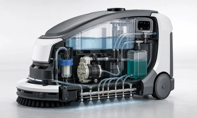
Reliable smart cleaning equipment depends on micro pumps matched to water, detergent, disinfectant, waste, target flow, pressure, priming, wetted materials, control, noise, duty cycle, and maintenance.
Micro Pumps for Smart Cleaning Equipment
Smart floor cleaners, robotic mops, window-cleaning devices, countertop appliances, sanitizing systems, and other automated equipment use micro pumps to move water, detergent, disinfectant, or waste. The pump may appear to be a small component, but it influences wetting uniformity, cleaning consistency, noise, battery life, leakage risk, and maintenance.
There is no single pump configuration for every cleaning device. Selection should begin with the fluid, required function, installed pressure, operating orientation, control method, and expected duty cycle. Performance must then be verified in the complete fluid path rather than inferred from a free-flow value.
Define the Cleaning Function
One product may need several fluid-handling operations:
Deliver clean water to a brush, pad, roller, or spray bar
Meter concentrated detergent into a water stream
Supply premixed cleaning solution
Generate pressure for one or more spray nozzles
Transfer dirty water to a waste tank
Drain a tray or docking station
Flush tubing after a cleaning cycle
Prime or purge the fluid path after tank replacement
Document the minimum, typical, and maximum flow for each operation. Also define the required dispensing time, number of outlets, operating frequency, and whether flow must remain constant as the tank empties or the device changes orientation.
Match the Pump Type to the Task
Diaphragm Liquid Pumps
Compact diaphragm pumps are often considered for transferring water or compatible cleaning solution and for supplying moderate pressure to a nozzle. Their internal valves and chamber contact the fluid, so every wetted material must be evaluated.
Particles, foam, deposits, and crystallized detergent can affect valve sealing or priming. A diaphragm pump selected for spraying should be tested at the actual nozzle restriction, not only under free-flow conditions.
Peristaltic Pumps
Peristaltic pumps keep the liquid inside replaceable tubing. They can be useful for detergent dosing, additive injection, or applications where an isolated and serviceable fluid path is valuable.
Flow varies with tube dimensions, speed, back pressure, temperature, and wear. The tubing is a consumable and requires a replacement and calibration plan.
Other Pump Options
Gear, piston, centrifugal, or other pump technologies may suit operating points outside the practical range of available micro diaphragm or peristaltic pumps. Selection depends on fluid viscosity, solids, pressure, noise, leakage tolerance, size, and cost.
Characterize Every Fluid
Provide the formulation or representative properties for clean water, detergent, disinfectant, rinse fluid, and recovered waste. Important information includes:
Chemical composition and concentration
Temperature range
Viscosity and surface tension
pH and solvent content
Foaming tendency
Particles, fibers, hair, or abrasive debris
Tendency to dry, crystallize, separate, or leave residue
Chemical compatibility must cover the pump chamber, diaphragm, valves, tubing, seals, fittings, tank materials, and any adhesive exposed to the fluid. Evaluate the actual concentration, temperature, pressure, exposure time, and cleaning sequence. A general material chart is only a starting point.
Waste liquid can be more difficult than the original cleaning solution because it may contain dirt, fibers, oils, food residue, or air. If the pump handles recovered liquid, test with representative contamination and define filtration requirements.
Calculate Flow and Pressure Together
The required flow depends on cleaning width, travel speed, surface type, nozzle pattern, and desired wetting level. Too little liquid may produce incomplete coverage; too much can leave excess water, increase drying time, or shorten battery runtime.
The installed fluid path creates resistance through filters, check valves, narrow tubing, manifolds, bends, elevation, and spray nozzles. As resistance rises, pump flow may decrease and motor load may increase.
Measure flow at the final outlet while recording inlet vacuum or outlet pressure, supply voltage, current, and pump temperature. Test both a new system and expected end-of-service conditions such as a partially loaded filter or aged valve.
Design for Priming and Tank Conditions
Cleaning equipment may start with an empty inlet tube, operate after a tank refill, or draw from a shallow tank as the device tilts. Define the maximum suction height, tube length, tank level, and allowed priming time.
Air leaks on the inlet side can prevent reliable priming even when no liquid leak is visible. Tank vents, caps, seals, fittings, and tube connections should therefore be included in testing.
Reservoir design should keep the inlet submerged without trapping unusable liquid. Baffles may help limit sloshing, while suitable outlet placement can reduce vortexing and air ingestion. Validate upright, tilted, turning, accelerating, and docking conditions relevant to the product.
Manage Foam, Bubbles, and Particles
Detergents may foam when agitated or when air enters the inlet. Bubbles can reduce delivered liquid volume, interrupt priming, alter sensor readings, and create an uneven spray pattern.
Possible controls include low-shear routing, controlled pump speed, submerged return paths, suitable tank geometry, leak-free inlet connections, and software that recognizes failed priming. Avoid recirculation layouts that continuously aerate the solution unless the system is designed for it.
Filters can protect pumps and nozzles from debris, but they add pressure loss and require service access. Size the filter for the expected contamination and test both clean and loaded conditions. A filter that is too fine or too small may cause flow loss long before it looks blocked.
Prevent Drips, Siphoning, and Leaks
Liquid movement after the pump stops can leave streaks, create puddles, drain the tank, or wet electronics. Causes include gravity, siphoning, residual pressure, valve leakage, tube recovery, and nozzle wetting.
Controls may include a suitable check or shutoff valve, pump reversal or suck-back, optimized nozzle geometry, controlled end-of-cycle speed, and fluid-path elevation management. Each added valve also creates resistance and may trap residue, so it must be tested in the complete system.
Use secondary containment, drainage paths, leak detection, and protected connectors where a failure could reach batteries, motors, sensors, or control boards. Test foreseeable loose-tube, cracked-tank, blocked-outlet, and overfill conditions.
Choose the Control Strategy
Simple equipment may run a DC pump at a fixed voltage. More advanced products can use PWM, analog speed control, stepper motion, or closed-loop feedback to match fluid delivery to travel speed, cleaning mode, or surface type.
Useful control functions may include:
Soft start to reduce current peaks and sudden spray
Fast priming followed by normal delivery speed
Flow adjustment for different cleaning modes
Pump delay coordinated with brushes or vehicle motion
Suck-back or valve closure at stop
Empty-tank, blockage, leak, or failed-prime detection
Automatic flushing after detergent use
Timed operation alone does not guarantee a fixed volume. Voltage, pressure, viscosity, temperature, air, and component wear can change delivery. Where dose or coverage is critical, consider calibration or feedback from flow, pressure, current, liquid, or tank-level sensing.
Control Noise, Vibration, and Power
In consumer and indoor equipment, pump noise can be as important as flow. Structure-borne vibration may be amplified by plastic housings, tanks, covers, or mounting brackets.
Evaluate the pump inside the final enclosure and across the full speed and pressure range. Resilient mounts, flexible tubing, adequate clearance, suitable speed control, and avoidance of rigid fluid connections can reduce transmitted vibration. Confirm that any soft mounting still supports the pump under shock and transport loads.
For battery-powered equipment, measure startup current and operating current at the real pressure rather than relying only on a nominal value. Include low-battery voltage, cold conditions, clogged filters, and repeated start-stop cycles in power and thermal testing.
Plan Cleaning and Maintenance
Residual detergent can thicken, crystallize, support biological growth, or make valves and tubing stick during storage. Define whether the fluid path should be rinsed, drained, or left filled after use.
Design service tasks so they are accessible and difficult to perform incorrectly:
Make filters and consumable tubing reachable.
Use secure, clearly routed connections.
Prevent tubing from kinking when covers close.
Provide a controlled flushing or drain sequence.
Verify output after pump, tube, valve, or filter replacement.
Record operating time, cycles, faults, and maintenance where useful.
Set replacement intervals from testing with the actual fluid, pressure, temperature, speed, and duty cycle. Do not assume a universal tubing or pump life.
Validation Checklist
All cleaning, disinfecting, rinsing, and waste fluids
Minimum and maximum flow at the final outlet
Clean and loaded filters
New and partially restricted nozzles
Full and nearly empty tank levels
Startup with dry and partially filled tubing
Upright, tilted, turning, docking, and transport orientations
Foam, bubbles, particles, fibers, and residue
Drip, siphon, suck-back, and shutoff behavior
Noise and vibration in the final enclosure
High, low, and changing supply voltage
Continuous, intermittent, and peak duty cycles
Blockage, empty-tank, inlet-leak, and fluid-leak faults
Flushing, storage, restart, and service procedures
Common Selection Mistakes
Selecting a pump from free-flow data alone
Treating clean water as representative of detergent or waste liquid
Ignoring nozzle, valve, and filter pressure loss
Assuming self-priming without testing the complete inlet path
Overlooking foam and air ingestion as the tank empties
Adding a fine filter without checking loaded pressure loss
Evaluating sound with the pump outside the product enclosure
Omitting drip, siphon, tilt, and low-battery tests
Making filters or tubing inaccessible for maintenance
Frequently Asked Questions
Which pump is suitable for smart cleaning equipment?
Diaphragm liquid pumps are often considered for water transfer and spray supply, while peristaltic pumps can suit detergent dosing or isolated fluid paths. The correct choice depends on fluid properties, flow, pressure, priming, noise, duty cycle, and maintenance.
Can one pump handle both water and detergent?
Possibly, but the full formulation and operating conditions must be compatible with every wetted material. Viscosity, foam, deposits, and storage behavior may also change pump performance.
Why does spray flow decrease during operation?
A loading filter, blocked nozzle, falling supply voltage, air entering the inlet, detergent residue, valve wear, or changing viscosity can reduce flow. Measure pressure, current, and outlet flow to help isolate the cause.
How can a cleaning device stop dripping?
Possible measures include a shutoff or check valve, pump suck-back, controlled stop speed, suitable nozzle design, and fluid-path elevation control. Validate the complete system because each measure has limitations.
Can a cleaning pump run dry?
Dry-running capability depends on the specific pump, duration, speed, temperature, and design. Even when the mechanism tolerates air, dry operation may interrupt delivery or accelerate wear, so empty-tank detection and run-time limits may still be useful.
Kamoer Smart Cleaning Equipment Support
Kamoer can help evaluate cleaning fluid, flow, pressure, priming, wetted materials, foam, filtration, control, noise, power, duty cycle, maintenance, and OEM integration for smart cleaning equipment.
Related Stories
Kamoer Fluid Tech (Shanghai) Co., Ltd.
pump@kamoer.com