

Micro Pumps for Smart Appliances
APPLICATIONS
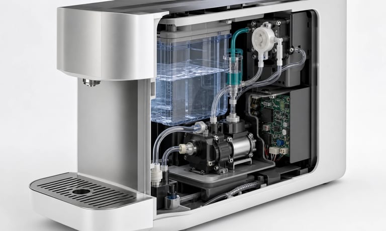
Reliable smart appliances depend on micro pumps matched to the fluid or gas, target flow, pressure or vacuum, wetted materials, priming, control, noise, power, leakage protection, duty cycle, and maintenance.
Micro Pumps for Smart Appliances
Smart appliances use compact pumps to move water, detergent, beverage ingredients, air, condensate, fragrance, cleaning fluid, and waste. Pumps may support dispensing, circulation, drainage, spraying, vacuum generation, sensor aspiration, or pneumatic actuation.
The pump affects appliance size, noise, power consumption, leakage risk, response time, maintenance, and user experience. Selection should begin with the required function and actual fluid path rather than a maximum flow value.
Define the Pump Function
Document every operating mode:
Transfer liquid from a tank or cartridge
Dispense a measured ingredient or cleaning agent
Circulate water through a heater, cooler, or sensor
Supply one or more spray nozzles
Drain condensate or waste
Draw air across a sensor
Generate vacuum or pressure for an actuator
Prime, purge, rinse, or dry the fluid path
Specify minimum and maximum flow, pressure or vacuum, run time, starts per day, direction, response time, and acceptable variation. Include refill, cleaning, standby, transport, and fault conditions.
Choose the Pump Technology
Peristaltic Pumps
Peristaltic pumps isolate liquid inside replaceable tubing. They can suit dosing, additive delivery, and applications where a serviceable fluid path, self-priming, or reversible flow is useful.
Flow changes with tube dimensions, speed, back pressure, temperature, and wear. Tubing requires compatibility, calibration, and replacement planning.
Diaphragm Liquid Pumps
Compact diaphragm liquid pumps can provide transfer or pressure for compatible fluids. The diaphragm, valves, chamber, seals, and ports contact the liquid.
Particles, deposits, air, and viscous fluids may affect valve operation and priming. Test with the actual liquid at the installed restriction.
Diaphragm Gas Pumps
Diaphragm gas pumps can support sensor aspiration, vacuum, pressure, air transfer, and pneumatic functions. Evaluate flow at the required vacuum or pressure rather than at free flow.
Moisture and condensation need specific management because a gas pump may not tolerate unrestricted liquid ingestion.
Characterize the Medium
For liquids, provide chemistry, concentration, viscosity, temperature, surface tension, particles, foam, volatility, and residue tendency. For gases, specify composition, humidity, aerosols, condensable vapors, and pressure.
Include cleaners, sanitizers, rinse fluids, mixed waste, and foreseeable contaminants. Compatibility must cover every wetted component under actual concentration, temperature, pressure, and exposure time.
Also consider adsorption, permeation, extractables, odor, taste, staining, and outgassing where the appliance function is sensitive. General material charts are only a starting point.
Define Flow, Pressure, and Vacuum Together
Filters, valves, tubing, fittings, sensors, heaters, manifolds, elevation, and nozzles create resistance. As restriction increases, pump flow may fall while current, temperature, or noise changes.
Measure output in the complete appliance while recording inlet vacuum or outlet pressure, voltage, current, and pump temperature. Include clean and aged filters, minimum and maximum tank levels, and the full environmental range.
Avoid oversizing. A pump that is too large may make small doses difficult, increase noise and power, or require excessive restriction.
Plan Priming and Air Management
Liquid systems may start with empty tubing after refill, storage, or service. Define suction height, inlet length, tank venting, pickup geometry, and acceptable prime time.
Air leaks can prevent priming without producing visible liquid leakage. Bubbles can also reduce dose consistency or interrupt a sensor.
Possible controls include secure inlet connections, submerged pickups, controlled prime cycles, liquid or bubble sensing, and software timeouts. Validate low tank level, tilt, transport, refill, and long-idle conditions.
Prevent Leaks, Drips, and Siphoning
Leaks can damage electronics, batteries, insulation, furniture, or flooring. Residual pressure, gravity, tube recovery, valve leakage, and nozzle wetting can continue moving liquid after the pump stops.
Use suitable fittings, tube retention, secondary containment, drainage, protected connectors, and leak detection according to risk. Check valves, shutoff valves, suck-back, controlled stop speed, and fluid-path elevation may help control dripping or siphoning.
Every added valve creates resistance and a possible residue trap. Test the complete system during operation, standby, tilt, refill, blockage, and power loss.
Select the Control Strategy
Control options may include fixed voltage, PWM, analog speed commands, stepper motion, or digital communication supported by the pump.
Smart functions can include:
Fast prime followed by normal operation
Recipe- or mode-based flow settings
Soft start and controlled stop
Closed-loop flow, pressure, vacuum, or level control
Empty-source, blockage, leak, or failed-prime detection
Automated flushing or drainage
Runtime and maintenance logging
Timed operation alone does not guarantee a fixed volume. Delivery may change with voltage, pressure, viscosity, temperature, air, and wear.
Control Noise and Vibration
Appliances operate near users, so tonal noise, clicking, and structure-borne vibration may be critical. Plastic panels, tanks, shelves, and rigid tubing can amplify pump vibration.
Evaluate the pump inside the final enclosure at every speed and restriction. Resilient mounts, flexible connections, adequate clearance, balanced routing, and suitable speed profiles may reduce transmission. Mounting must remain secure through transport and shock.
Manage Power and Heat
Battery-powered and energy-sensitive appliances should be evaluated at the real operating point. Measure startup current, steady current, low-voltage behavior, standby consumption, and simultaneous loads.
Test continuous, intermittent, and repeated cycles inside the final enclosure until temperatures stabilize. Include blocked lines, loaded filters, warm ambient conditions, and reduced ventilation.
Do not assume an open-bench temperature or short test represents long-term appliance operation.
Design for Cleaning and Maintenance
Fluids may dry, crystallize, support biological growth, or leave sticky deposits during idle periods. Define whether the path is flushed, drained, kept wet, or replaced.
Make filters, tubing, tanks, traps, and pump modules accessible.
Prevent incorrect tube routing or reversed connections.
Provide controlled rinse and drain sequences.
Verify output after service.
Record cycles, runtime, faults, and replacement history where useful.
Set service intervals from tests using the actual medium, temperature, pressure, speed, and duty cycle. Do not assume a universal pump or tubing life.
Validate the Complete Appliance
Production fluid or gas and all cleaning media
Minimum and maximum flow, pressure, and vacuum
Full tank-level, temperature, and voltage range
Clean and loaded filters
Dry and partially filled startup
Bubbles, foam, particles, humidity, and condensation
Upright, tilted, transported, and stored orientations
Drip, siphon, leak, blockage, and power-loss behavior
Noise and vibration in the final enclosure
Continuous, intermittent, and peak duty cycles
New and aged tubing, valves, diaphragms, and seals
Cleaning, maintenance, and restart procedures
Sensor feedback and fault-detection thresholds
Common Selection Mistakes
Selecting from free-flow data only
Testing with water instead of the real medium
Ignoring filters, valves, nozzles, and elevation
Assuming self-priming without testing the inlet path
Evaluating sound with the pump outside the enclosure
Ignoring low supply voltage and simultaneous loads
Omitting tilt, storage, drip, and power-loss tests
Relying on generic material compatibility
Hiding consumable parts behind difficult service access
Skipping representative life and thermal testing
Frequently Asked Questions
Which micro pump is best for a smart appliance?
There is no universal best type. Peristaltic, diaphragm liquid, and diaphragm gas pumps serve different functions. Medium, flow, pressure, control, noise, power, duty cycle, and maintenance determine the choice.
How can pump noise be reduced in an appliance?
Test inside the final enclosure, then evaluate mounting, flexible tubing, clearance, pump speed, operating pressure, and structural resonance. Noise cannot be judged from the pump alone.
Can one pump handle several appliance functions?
Sometimes, but shared use can complicate valves, control, contamination, cleaning, and fault handling. Compare the shared circuit with separate pumps at system level.
Can a smart appliance detect a blocked pump line?
Flow, pressure, vacuum, motor current, speed, liquid, or level sensing may help. Detection thresholds must be established with representative faults and component tolerances.
How long should an appliance pump last?
Service life depends on the pump model, load, medium, pressure, temperature, speed, starts, and environment. Determine the maintenance plan through representative life testing.
Kamoer Smart Appliance Pump Support
Kamoer can help evaluate medium, flow, pressure, vacuum, wetted materials, priming, control, noise, power, leakage protection, duty cycle, testing, and OEM integration for smart appliances.
Related Stories
Kamoer Fluid Tech (Shanghai) Co., Ltd.
pump@kamoer.com