

Micro Pumps for Gas Sampling Systems
APPLICATIONSWATER ANALYSIS WATER TREATMENT
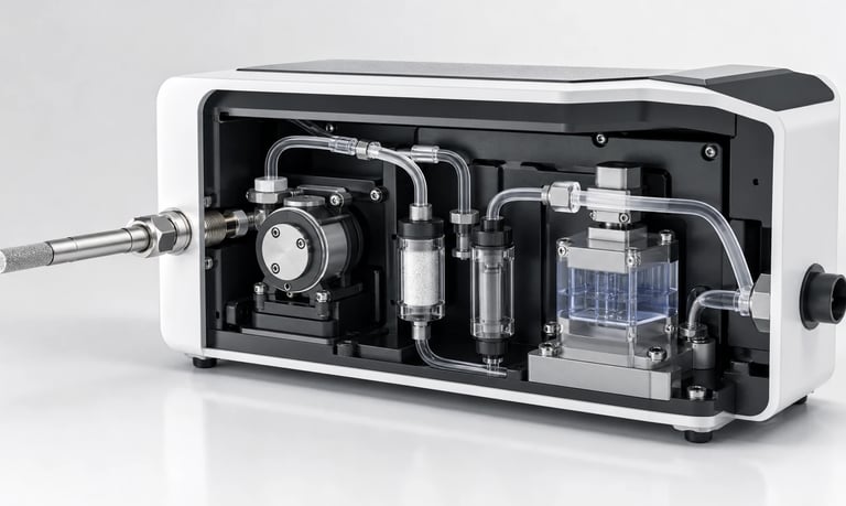
Reliable gas sampling depends on micro pumps matched to target flow, inlet vacuum, gas composition, wetted materials, leakage, moisture, filtration, altitude, control, power, duty cycle, and maintenance.
Micro Pumps for Gas Sampling Systems
Gas sampling systems use micro pumps to draw air or process gas through probes, tubing, filters, dryers, sensors, and analysis cells. Applications include environmental monitoring, indoor air measurement, emissions analysis, leak detection, headspace sampling, and portable detection equipment.
Pump selection influences sample flow, response time, measurement stability, leakage, condensation risk, power consumption, noise, and maintenance. A suitable gas sampling pump must be evaluated at the required flow and inlet vacuum in the complete sampling path. Free-flow data alone does not describe installed performance.
Define the Sampling Method
Start by documenting what the pump must do:
Draw a continuous sample through an analyzer
Pull a timed sample into a bag, tube, or chamber
Aspirate gas across a sensor
Purge the sampling path before measurement
Transfer calibration or zero gas
Generate vacuum for a fluidic function
Exhaust analyzed gas to a safe location
Specify minimum, typical, and maximum flow, required response time, sampling duration, duty cycle, and whether flow must remain constant as filters load or atmospheric pressure changes.
Also define where flow is referenced. Volumetric flow at ambient conditions, flow at the sensor, and standardized flow are not interchangeable without accounting for pressure and temperature.
Why Diaphragm Gas Pumps Are Common
Compact diaphragm gas pumps use a reciprocating diaphragm and valves to move gas while separating the pumping chamber from the drive mechanism. They can provide suction, pressure, or both in a small package and are widely considered for sampling instruments.
The gas contacts the diaphragm, valve materials, chamber, ports, and connected tubing. These components can affect chemical compatibility, adsorption, outgassing, leakage, and sample integrity.
Pump curves, valve behavior, pulsation, motor type, and thermal performance vary by model. Select against the real operating point rather than assuming that all diaphragm gas pumps behave similarly.
Specify Flow Together with Vacuum
Every element upstream of the pump creates resistance. Common sources include:
Sample probes and long tubing
Fine filters and particulate loading
Hydrophobic membranes
Water traps and dryers
Valves, fittings, and flow restrictors
Sensor cells and analytical columns
Small-diameter or sharply bent tubing
As inlet resistance increases, the pump operates at a deeper vacuum and its flow may fall. Motor current, temperature, noise, and pulsation can also change.
Estimate the pressure loss of each component, then measure the assembled system. Check flow at the sensor while recording inlet vacuum, supply voltage, current, and pump temperature. Include both clean and end-of-service filter conditions.
Avoid selecting a much larger pump and then wasting most of its capacity through a severe restriction. That approach may increase noise, power, heat, and control difficulty.
Characterize the Sample Gas
Provide the gas composition and expected concentration range, including carrier gas, target compounds, interferents, calibration gas, cleaning gas, and possible contaminants.
Important conditions include:
Temperature and humidity
Corrosive or reactive components
Solvent or fuel vapors
Aerosols, dust, and droplets
Condensable compounds
Flammable or toxic gases
Oxygen concentration
Expected pressure and exposure time
Compatibility must cover every wetted material under actual concentration, temperature, pressure, humidity, and duration. A general elastomer chart is only an initial screening tool.
Where a gas may create a hazardous atmosphere, use only equipment with documentation suitable for the specific installation and applicable requirements. Pump selection does not replace system-level risk assessment, ventilation, containment, or ignition-control design.
Protect Sample Integrity
The pump and tubing can alter the sample before it reaches the sensor. Potential effects include adsorption, desorption, gas permeation, outgassing, condensation, chemical reaction, particle shedding, and carryover from a previous sample.
Place the pump upstream or downstream of the analyzer according to the measurement method and acceptable contamination risk. A downstream pump can keep some samples from contacting the pump before analysis, but it also changes pressure inside the sensor path. An upstream pump may simplify outlet conditions while exposing the sample to pump materials first.
Validate the complete path with representative gases and the intended analytical method. Material compatibility alone does not prove acceptable recovery or response time for trace measurements.
Control Leakage
Small leaks can dilute the sample, admit ambient air, release hazardous gas, or prevent the system from reaching its operating vacuum. An inlet-side leak may draw air inward without producing a visible outward leak.
Review pump-head sealing, fittings, tube ends, manifolds, sensor cells, filter housings, water traps, and valve bypass paths. Define an allowable leak rate from measurement sensitivity and safety requirements.
Use an appropriate pressure-decay, vacuum-decay, tracer-gas, or functional test during development, production, and after service. Software may compare pump command, measured flow, vacuum, and current to distinguish a leak from a blockage or worn pump.
Manage Moisture and Condensation
Warm humid gas can condense as it passes through cooler tubing, filters, or sensor cells. Droplets may block flow, change analyte concentration, damage sensors, contaminate the pump, or cause unstable readings.
Possible controls include:
Heated probes or sample lines
Insulated routing
Water traps and controlled drainage
Hydrophobic filters
Membrane dryers or other conditioning methods
Orientation that prevents pooling
Moisture or liquid detection
Every conditioning component changes pressure loss and may adsorb or remove target compounds. Validate its effect on both pump capacity and measurement performance.
Do not assume a gas pump can tolerate unrestricted liquid ingestion. If condensation can reach the pump, confirm the specific model's limits and include fault handling.
Select and Monitor Filtration
Filters protect pumps and sensors from dust, aerosols, and droplets. Their resistance rises as contamination accumulates, reducing flow and increasing inlet vacuum.
Define filter medium, pore size, area, chemical behavior, clean pressure loss, maximum loaded pressure loss, and replacement interval. Check whether the filter adsorbs the target gas or releases interfering compounds.
Use representative dust or aerosol loading during validation. A visually clean filter may already create unacceptable resistance. Pressure, flow, runtime, or pump-current monitoring can support maintenance alerts, but thresholds must be established from system test data.
Account for Altitude and Ambient Conditions
Atmospheric pressure and gas density change with altitude. This can affect volumetric flow, mass flow, available vacuum, pump temperature, and calibration. Temperature also changes motor performance, valve response, material flexibility, battery capacity, and condensation behavior.
Validate the intended range of altitude, barometric pressure, ambient and sample temperature, humidity, enclosure temperature, supply voltage, dust, vibration, and transport conditions.
Test the pump inside the final enclosure because ventilation, mounting, insulation, and nearby electronics influence temperature and sound.
Control Flow and Pulsation
Fixed-voltage operation can be adequate where the fluid path and environment remain stable. Variable-speed control using PWM, analog commands, or another supported method can provide adjustable flow or faster purge followed by quieter sampling.
Closed-loop control may use a flow sensor, differential-pressure sensor, vacuum sensor, or mass-flow measurement. Sensor range, response time, added restriction, gas compatibility, and calibration drift must be included in the design.
Diaphragm motion produces periodic flow and pressure variation. Pulsation can affect sensitive sensors and flow readings. Possible controls include a suitable operating speed, compliant volume, compatible damper, flow restrictor, or signal filtering. Verify that any added volume does not create unacceptable response delay or carryover.
Balance Response Time and Sample Volume
The time needed to replace gas in a sampling path depends on internal volume and effective flow. Long tubing, large filters, traps, and dampers increase the volume that must be purged.
Nominal volume divided by flow provides only a first estimate. Mixing, adsorption, dead zones, diffusion, and sensor response can extend the time required for a stable reading.
Validate step response using representative gas concentration changes. Define purge time, measurement window, and fault timeout from actual data rather than pump flow alone.
Manage Power, Noise, and Vibration
Portable and battery-powered instruments must account for startup current, operating current at the actual vacuum, duty cycle, and low-voltage behavior. A loaded filter or blocked line may increase current and heat even while sample flow falls.
Pump vibration can couple into housings, sensors, microphones, optical benches, or tubing. Evaluate sound and vibration in the assembled device across all speeds and restrictions.
Resilient mounts, flexible tubing, adequate clearance, suitable speed control, and balanced routing may reduce transmission. Confirm that soft mounting still supports the pump during transport and shock.
Plan Fault Detection and Maintenance
Useful diagnostic inputs include measured flow, inlet vacuum, motor current or speed feedback, filter runtime, moisture detection, valve state, and pump temperature.
Fault logic should distinguish an open inlet, blocked probe, loaded filter, leaking fitting, liquid ingestion, failed valve, worn pump, and sensor error where practical.
Make filters, traps, tubing, and pump modules accessible without disturbing sensitive calibration. Record operating hours, cycles, pressure, flow, faults, and service history. Establish replacement intervals from representative life testing rather than a universal service-life assumption.
Validation Checklist
Production, calibration, zero, and interfering gases
Minimum and maximum flow at the sensor
Required inlet vacuum and outlet pressure
Clean and realistically loaded filters
Full tubing length, probe, valves, dryer, and analysis cell
System leakage and valve crossover
Adsorption, carryover, permeation, and outgassing
Temperature, humidity, altitude, and condensation
Dry gas, humid gas, aerosols, and foreseeable droplets
Startup, purge, sample, standby, and shutdown modes
Response time after a concentration step
Pulsation at the sensor and flow measurement point
Minimum and maximum supply voltage
Continuous and intermittent duty cycles
Blockage, leak, liquid-ingestion, and power-loss faults
New and aged valves, diaphragms, filters, and tubing
Common Selection Mistakes
Selecting from maximum free-flow data only
Ignoring filter loading and long sample lines
Specifying flow without its vacuum operating point
Assuming zero visible leakage means an airtight inlet path
Overlooking adsorption and outgassing in trace measurements
Allowing condensate to reach a pump not designed for it
Adding a damper without checking response time and carryover
Testing only at room temperature and sea level
Measuring noise with the pump outside the enclosure
Omitting maintenance access and post-service leak testing
Frequently Asked Questions
Which pump is commonly used for gas sampling?
A compact diaphragm gas pump is often considered because it can generate flow and vacuum in a small package. The required operating point, gas composition, moisture, leakage, power, and service life determine suitability.
Why does gas-sampling flow decrease over time?
A loaded filter, blocked probe, condensate, leaking valve, worn diaphragm, restricted tubing, or falling supply voltage can reduce flow. Measure both flow and vacuum to help identify the cause.
Should the pump be installed before or after the sensor?
Either arrangement may be used. Pump placement affects sample contact with pump materials, sensor pressure, leak direction, and exhaust handling. Choose according to the measurement method and validate the complete path.
Can a gas pump handle condensation?
Only if the specific pump and system are designed for the expected moisture or liquid exposure. Water traps, hydrophobic filters, heated lines, drainage, or detection may be required.
Does altitude affect a gas sampling pump?
Yes. Atmospheric pressure and gas density change with altitude, which can alter flow, vacuum, mass delivery, temperature, and calibration.
Kamoer Gas Sampling Support
Kamoer can help evaluate target flow, inlet vacuum, gas composition, wetted materials, leakage, moisture, filtration, pulsation, control, power, noise, duty cycle, and OEM integration for gas sampling systems.
Related Stories
Kamoer Fluid Tech (Shanghai) Co., Ltd.
pump@kamoer.com