

How Viscosity Affects Micro Pump Performance
MICRO PUMP BASICS
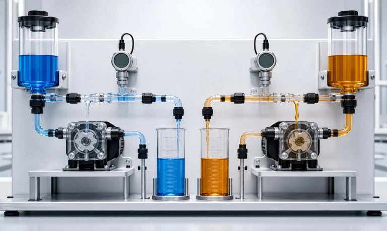
Liquid viscosity affects micro pump performance by changing fluid-path resistance, chamber or tube refill, valve response, pressure demand, motor load, priming, pulsation, heat generation, and the relationship between pump speed and delivered flow.
How Viscosity Affects Micro Pump Performance
Viscosity describes a fluid's resistance to flow. As viscosity increases, a micro pump usually needs more time and energy to draw liquid in, move it through narrow passages, and discharge it against system resistance. Delivered flow may fall, motor load may rise, priming may take longer, and dosing may become less repeatable.
The effect is not determined by viscosity alone. Pump technology, speed, inlet conditions, tubing diameter, valve geometry, temperature, pressure, and fluid behavior all matter. Performance data measured with water should not be treated as proof of performance with a thicker production liquid.
Understand What the Viscosity Value Means
Dynamic viscosity is commonly reported in mPa.s or cP; for practical comparison, 1 mPa.s equals 1 cP. Kinematic viscosity is reported in units such as mm2/s or cSt and also depends on density. These values are related but are not interchangeable without the fluid density.
A viscosity value is useful only when its measurement conditions are known. Record:
Fluid temperature
Measurement method and instrument
Shear rate or spindle and speed, where relevant
Fluid concentration and batch
Time after mixing or preparation
Presence of particles, bubbles, or separated phases
Supplier values can support early screening, but representative measurements are preferable when formulation, storage, or temperature varies.
Viscosity May Change During Pumping
Newtonian liquids have approximately constant viscosity at a given temperature across the relevant shear range. Many real products are non-Newtonian.
Shear-thinning fluids become less viscous as shear rate increases. Shear-thickening fluids become more viscous. Thixotropic fluids become less viscous over time under shear and rebuild structure while resting. Yield-stress materials may not move until applied stress exceeds a threshold.
This means one catalog viscosity number may not predict behavior in a reservoir, inlet tube, pump chamber, check valve, and nozzle. The fluid can experience different shear conditions in each location.
After a long idle, a thixotropic or yield-stress product may require a larger startup force than it needs during steady operation. Test both startup and stabilized flow rather than recording only an average after the system is already moving.
Higher Viscosity Increases Fluid-Path Resistance
Pressure loss increases as fluid becomes more viscous. The effect becomes especially important in small-bore tubing, long lines, narrow fittings, filters, check valves, manifolds, and dispensing nozzles.
For simple laminar flow through a round tube, pressure loss is strongly affected by viscosity, length, flow, and tube radius. The relationship is useful for understanding trends, but a complete micro-pump system rarely behaves like one straight, rigid tube. Flexible tubing, pulsating flow, valves, entrances, contractions, and non-Newtonian behavior require measurement.
Reducing resistance may involve:
Shortening the fluid path
Increasing the internal diameter
Removing unnecessary fittings and sharp bends
Selecting valves and sensors with adequate passage size
Using a larger or lower-resistance filter
Locating the pump close to the source reservoir
Changing one restriction can be more effective than increasing pump size or speed.
Inlet Performance Often Becomes the Limit
The pump must refill before it can deliver the next volume of liquid. High viscosity slows flow into a peristaltic tube, diaphragm chamber, piston chamber, or other displacement volume.
If refill is incomplete, actual displacement per cycle falls. Increasing speed gives the liquid even less time to enter, so flow may stop rising proportionally with speed. The speed-to-flow curve can flatten, and variation between cycles can increase.
Excessive inlet resistance may also cause:
Long or failed priming
Partial tube or chamber filling
Air entering through imperfect connections
Collapse of soft inlet tubing
Bubble growth where local pressure becomes low enough
Unstable sound, vibration, or motor current
Measure inlet vacuum at the pump port under the worst expected viscosity, temperature, reservoir level, and speed. A line that works with water may be too restrictive for the production fluid.
Outlet Pressure Demand Also Rises
On the outlet side, the pump must overcome resistance from the fluid path plus static elevation and any process pressure. As viscosity rises, the pressure required to maintain a given flow usually rises as well.
If the required pressure approaches the practical capability of the pump or tubing, flow may fall and component stress may increase. A diaphragm pump may show more internal leakage or altered valve behavior. A peristaltic system may experience tube expansion, slip, reduced volumetric efficiency, or backflow if occlusion is inadequate.
Test the complete outlet path, including the production nozzle, valves, filter, sensor, elevation, and longest tubing configuration. Include normal operation, startup against residual pressure, and realistic partial restrictions.
Pump Type Changes the Viscosity Response
Peristaltic Pumps
A peristaltic pump isolates the liquid inside tubing. This can simplify fluid compatibility and maintenance, but viscous-liquid performance depends on the tube reopening fully after each roller pass.
Higher viscosity and inlet vacuum can slow refill. Larger-bore inlet tubing, shorter suction length, lower speed, and suitable tube recovery can help. The pump must also provide enough torque to compress the tube while overcoming outlet pressure.
Diaphragm Liquid Pumps
A diaphragm liquid pump relies on chamber filling and check-valve response. Viscous liquid can slow both processes. Sticky fluids, fibers, particles, or crystals may prevent valves from seating consistently.
The result can be reduced flow, longer priming, pressure variation, or loss of repeatability. Valve geometry and material response are therefore as important as nominal motor power.
Other Positive-Displacement Pumps
Gear, piston, syringe, and progressive-cavity designs can suit some viscous applications, but each introduces different limits involving leakage, sealing, shear, particles, pulsation, cleaning, and dose resolution.
Do not choose only by a maximum viscosity claim. Compare performance at the required flow, pressure, temperature, and duty cycle using the actual fluid path.
Pump Speed Does Not Guarantee Proportional Flow
With a low-viscosity test liquid and low system resistance, flow may appear approximately proportional to speed over part of a pump's range. Higher viscosity can narrow that usable range.
At low speed, static friction, valve opening, yield stress, or leakage may affect the minimum reliable flow. At high speed, incomplete refill and increased pressure loss may reduce displacement per cycle.
Create a speed-to-flow curve for each important condition rather than using a single conversion factor. Include:
Minimum, typical, and maximum viscosity
Cold startup and stabilized temperature
Minimum and maximum outlet pressure
Full and low reservoir level
New and aged tubing or valves
Production supply-voltage limits
A curve that bends away from proportional behavior is useful design information, not merely a calibration error.
Motor Load and Heat Can Increase
Moving a viscous liquid can require more torque. Motor current may increase as the pump works against higher inlet and outlet resistance. Driver losses, motor heating, and pump-head temperature can also rise.
Current is not a direct measurement of flow. High current could indicate viscous fluid, a blocked outlet, excessive tube compression, mechanical wear, or low temperature. Low current does not prove that liquid is moving; the source may be empty or an inlet connection may be drawing air.
Measure current, voltage, speed, pressure, flow, and temperature together. Allow the enclosed system to reach thermal equilibrium during continuous or repeated operation. Verify startup at the minimum available voltage and worst fluid condition.
Dosing Accuracy and Repeatability May Shift
Timed pump operation assumes a sufficiently stable relationship between command duration and delivered flow. Viscosity changes can disturb that relationship through incomplete refill, valve delay, pressure change, elastic expansion, bubbles, and startup transients.
For small doses, the time required to build pressure or begin fluid motion may represent a large part of the command. The first dose after a long idle may differ from later doses.
Evaluate:
Individual dose mass or volume
First dose after idle
Short and long command durations
Repeated-dose mean and variation
Different reservoir levels
Temperature and viscosity extremes
Pressure before and after the pump stops
Where tighter control is required, consider gravimetric, flow, level, or pressure feedback. Calibration should be tied to defined operating conditions and reviewed after changes to fluid lot, tubing, valves, or temperature.
Priming and Bubble Behavior Can Change
Viscous fluids move slowly during priming and can retain air bubbles. Small inlet leaks may pull air into the line without showing an outward liquid leak. Trapped gas compresses under pressure and can delay delivery or create an uneven dose after the pump stops.
Prime using a validated speed and timeout. A high speed may worsen incomplete refill or aeration, while a very low speed may not overcome startup resistance.
Reservoir geometry, pickup position, fittings, tube routing, and degassing method can be as important as the pump. Confirm priming from a dry path, a partially filled path, and after the longest expected idle period.
Pulsation and Pressure Ripple May Become More Noticeable
Positive-displacement micro pumps deliver fluid in cycles. Higher viscosity and line resistance can increase the amplitude or duration of pressure changes associated with each cycle. Flexible tubing may store and release energy, shifting the timing between pump motion and nozzle flow.
The visible output can become uneven even when average flow remains acceptable. This matters for spraying, coating, mixing, analytical dosing, and any process sensitive to instantaneous flow.
Lower speed, additional pump-head rollers, optimized tubing compliance, a pulsation damper, or a different pump technology may help. Any damping device adds internal volume and can affect response, cleaning, and trapped gas, so validate the full cycle.
Temperature Can Dominate the Result
Many liquids become substantially more viscous as temperature falls. A system validated only at room temperature may have poor cold-start flow even if its normal steady-state performance is acceptable.
Heating may reduce viscosity, but it can also change product stability, evaporation, chemical compatibility, tubing properties, permeation, and cleaning requirements. Local heat from the motor or enclosure may gradually change flow during operation.
Measure fluid temperature near the pump inlet and, where relevant, at the outlet. Test the minimum and maximum real temperatures as well as the transition between them. Do not use ambient air temperature as a substitute for fluid temperature.
Viscosity Affects Shear and Product Condition
High pressure loss through narrow gaps, valves, tubing, and nozzles can create shear. Depending on the fluid, shear may alter emulsions, polymers, cells, foams, or suspensions. Shear-thinning behavior may temporarily improve flow while also changing the product.
Evaluate the property that matters after pumping, not only the delivered volume. This may include particle distribution, cell viability, foam, appearance, concentration, or another application-specific measure.
Recirculation and repeated passes can expose the fluid to much more shear than one transfer. Include the actual number of passes and operating time in validation.
Build a Representative Viscosity Test
Use the production liquid whenever practical. If a substitute is required, matching one room-temperature viscosity value is not enough. The substitute should reproduce the relevant temperature response, shear behavior, density, surface tension, particles, and material interaction.
For each test condition, record:
Fluid identity, lot, preparation, and age
Viscosity and temperature
Pump speed and control command
Flow or individual dose
Inlet vacuum and outlet pressure
Motor voltage, current, and temperature
Prime time and bubble behavior
Pulsation or instantaneous flow where relevant
Performance after idle and during extended operation
Use multiple pump and consumable samples when variation matters. Repeat testing after representative tubing, diaphragm, valve, or seal aging.
Viscosity Validation Checklist
Viscosity units, method, temperature, and shear conditions
Newtonian or non-Newtonian behavior
Fluid-lot and concentration variation
Cold start, normal operation, and maximum temperature
Minimum, typical, and maximum flow or dose
Speed-to-flow curves across the operating range
Final inlet length, diameter, fittings, and reservoir level
Inlet vacuum and tube collapse resistance
Final outlet path, nozzle, filter, valves, and elevation
Outlet pressure and residual pressure at restart
Prime time, bubbles, and dry-path recovery
Motor current, supply voltage, torque, and thermal stabilization
Pulsation and individual-dose repeatability
Product quality after pumping and recirculation
Cleaning, idle, separation, curing, and restart behavior
New and aged fluid-path components
Blockage, empty source, inlet leak, and sensor faults
Common Viscosity Mistakes
Using water-test flow as the production flow
Reporting viscosity without temperature or measurement method
Treating a non-Newtonian fluid as one fixed viscosity
Increasing speed without checking chamber or tube refill
Focusing on outlet pressure while ignoring inlet vacuum
Using narrow fittings inside otherwise adequate tubing
Assuming motor current proves that fluid is flowing
Calibrating only after the pump and fluid have warmed up
Ignoring the first dose after a long idle
Selecting from a maximum viscosity claim without system testing
Frequently Asked Questions
Does higher viscosity always reduce pump flow?
It often reduces flow at a given speed because inlet refill and fluid-path resistance worsen, but the size of the effect depends on pump type, tubing, pressure, temperature, and fluid behavior.
Why does micro pump flow stop increasing with speed?
The pump chamber or peristaltic tube may not refill completely before the next cycle. Inlet restriction, high viscosity, low temperature, or trapped air can contribute.
Can motor current be used to compensate for viscosity?
Current can indicate load change, but it is not a direct viscosity or flow measurement. Pressure, occlusion, wear, blockage, voltage, and temperature also affect current.
Why is the first dose after idle different?
The fluid may rebuild structure, cool, settle, or create residual pressure during idle. The pump may also need time to refill the path and compress trapped gas.
Should a viscous fluid be heated before pumping?
Only if controlled heating is acceptable for the product and system. Validate stability, materials, evaporation, safety, cleaning, and fault limits before using heat to reduce viscosity.
How should viscosity performance be specified to a pump supplier?
Provide the fluid, viscosity range with temperature and test method, flow or dose, inlet and outlet path, pressure, duty cycle, control needs, cleaning process, and expected operating extremes.
Kamoer Viscosity and Pump Performance Support
Kamoer can help evaluate fluid viscosity, pump type, speed range, inlet refill, outlet pressure, tubing and valve geometry, motor load, dosing behavior, temperature, control, and representative OEM testing.
Related Stories
Kamoer Fluid Tech (Shanghai) Co., Ltd.
pump@kamoer.com