

How to Select Wetted Materials for a Diaphragm Liquid Pump
TUBING & CHEMICAL
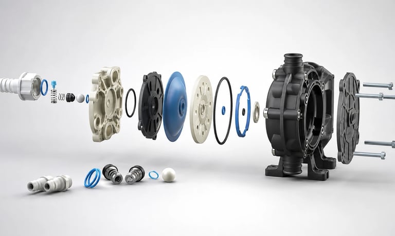
Wetted-material selection for a diaphragm liquid pump must cover every surface exposed to product, cleaner, rinse, vapor, and mixed waste while accounting for concentration, temperature, pressure, exposure time, cyclic diaphragm and valve motion, permeation, extraction, corrosion, and dynamic validation.
How to Select Wetted Materials for a Diaphragm Liquid Pump
Wetted materials are every material that can contact the pumped liquid, vapor, cleaner, rinse, or residue. In a diaphragm liquid pump, this may include the diaphragm, inlet and outlet valves, pump chamber, seals, ports, fittings, adhesives, sensor surfaces, and sometimes lubricant or backing layers if a failure exposes them.
Material selection cannot be made from a fluid name alone. Compatibility changes with concentration, temperature, pressure, exposure time, mechanical stress, cleaning, sterilization, impurities, and whether the material is repeatedly flexed or compressed.
A chemical chart is useful for screening, but the final pump should be tested dynamically with the exact material grades and realistic fluids. A material that survives static immersion may still swell, harden, crack, permeate, shed, or lose valve performance during pumping.
Build a Complete Wetted-Material List
Start with a fluid-path drawing and bill of materials. Identify every surface the fluid can reach during normal operation, priming, cleaning, pressure cycling, shutdown, leakage, and foreseeable faults.
The list may include:
Diaphragm fluid-side layer
Diaphragm substrate, reinforcement, or bonded layers
Inlet and outlet valve elements
Valve seats and retainers
Pump chamber and cover
Port inserts and manifolds
O-rings, gaskets, and static seals
Tubing and tube fittings
Adhesives, potting, coatings, and thread sealants
Filters, sensors, dampers, and shutoff valves
Reservoir pickup and nozzle
Metal springs, fasteners, or inserts exposed to fluid
Do not assume a component described by one main material contains no additives, colorants, plasticizers, fillers, reinforcement, bonding agents, or processing residues.
Request exact part and material grades where the application requires controlled compatibility. A broad label such as silicone, EPDM, FKM, PTFE, stainless steel, or engineering plastic does not define a complete formulation or finished component.
Define Every Fluid Exposure
The production fluid is only one exposure. List all liquids and vapors that can contact the pump during its life.
Include:
Product or reagent
Minimum and maximum concentration
Solvents and carriers
Acids, bases, salts, oxidizers, and additives
Preservatives, surfactants, dyes, oils, and fragrances
Cleaning and sanitizing agents
Rinse water or buffer
Calibration and test fluids
Mixed product and cleaner
Waste or reaction by-products
Air, humidity, or vapor during idle
Impurities can matter. Trace solvent, chlorine, ozone, oil, particles, or residual cleaner may attack a material even when the main fluid appears compatible.
Document fluid lot, preparation, age, pH where relevant, and whether concentration changes through evaporation, freezing, mixing, or process reaction.
For proprietary fluids, obtain enough composition and hazard information to evaluate materials safely. A trade name alone is rarely sufficient.
Define Temperature, Pressure, and Time
Compatibility data must be tied to conditions.
Record:
Minimum, normal, and maximum fluid temperature
Ambient and enclosure temperature
Cleaning or sanitizing temperature
Operating inlet vacuum and outlet pressure
Pressure pulses and blockage condition
Continuous contact time
Idle time while filled
Number and duration of cleaning cycles
Storage and transport exposure
Wet-dry and thermal cycles
Higher temperature often accelerates chemical interaction, permeation, extraction, and stress relaxation. Pressure can drive fluid into interfaces and increase leakage or permeation. Long idle exposure may be more damaging than short pumping exposure.
A supplier's maximum temperature is not proof of compatibility with a particular fluid at that temperature. Mechanical flexing, pressure, and material aging can reduce the useful system limit.
Understand the Diaphragm's Mechanical Demands
The diaphragm is both a wetted barrier and a cyclic mechanical component. It must flex through the intended stroke while maintaining shape, strength, sealing, and chemical resistance.
Chemical exposure may cause:
Swelling that changes stroke volume or creates rubbing
Softening that increases deformation or fatigue
Hardening that reduces flexibility
Cracking or edge failure
Delamination of multilayer construction
Permeation into the drive side
Extraction of additives
Mass or dimensional change
Pressure, stroke, speed, temperature, and clamp geometry interact with chemistry. A diaphragm that appears acceptable after immersion may fail when flexed repeatedly under differential pressure.
Use the exact finished diaphragm in dynamic testing. Flat sheet data does not fully represent molded shape, thickness transitions, bonding, reinforcement, or assembly stress.
Understand Valve-Material Demands
Diaphragm pumps depend on inlet and outlet valves opening and resealing every cycle. Small changes in valve stiffness, shape, surface, or friction can cause large changes in priming, suction, flow, pressure, and leakage.
Chemical exposure may lead to:
Valve swelling or curling
Stiffening and delayed opening
Softening and poor resealing
Tackiness or adhesion to the seat
Surface deposits
Cracking or tearing
Extraction or contamination
Dimensional change
Particles, crystals, fibers, and sticky residue can compound material effects.
Test prime time, inlet vacuum, flow, outlet pressure, backflow, and restart after idle. A valve may pass a static compatibility check yet become too slow or leaky for the pump cycle.
Valve and seat materials must be evaluated as a pair. Surface finish, contact geometry, preload, and fluid wetting influence sealing.
Evaluate Elastomers by Exact Grade
Elastomers are commonly used in diaphragms, valves, seals, and flexible connectors. Their performance depends on polymer type, formulation, cure, hardness, fillers, additives, and manufacturing process.
Relevant behaviors include:
Volume swell or shrinkage
Hardness change
Tensile and tear-property change
Compression set
Flex-fatigue performance
Permeation
Extractables and leachables
Low- and high-temperature flexibility
Adhesion or tackiness
Material-family names can support initial screening, but different grades within a family may respond differently.
Do not assume that a seal grade is suitable for a dynamically flexing diaphragm, or that a diaphragm grade is suitable for a precision check valve. The mechanical role changes the acceptance criteria.
Evaluate the finished component after realistic molding, curing, cleaning, and aging.
Evaluate Plastics and Fluoropolymers
Rigid and semi-rigid polymers may be used for pump chambers, covers, manifolds, fittings, valve retainers, and diaphragm layers.
Potential failure modes include:
Swelling or dimensional change
Softening or loss of strength
Environmental stress cracking
Crazing
Permeation
Solvent absorption
Warping
Creep under fastener or pressure load
Extraction of additives
Surface adsorption or staining
Stress cracking is especially important because a plastic part may tolerate a fluid without load but crack when combined with molded-in stress, threads, press fits, screw torque, or pressure cycling.
Fluoropolymer materials can offer broad chemical resistance in many applications, but grade, processing, mechanical flexibility, permeability, sealing, bonding, and cost still require review. Broad resistance does not eliminate the need for exact-condition validation.
Inspect molded features, welds, threads, inserts, and sharp corners after chemical and pressure exposure.
Evaluate Metals and Corrosion
Metals may appear in springs, inserts, fittings, fasteners, sensors, valve parts, or pump chambers. Alloy designation, surface condition, heat treatment, welds, coatings, and galvanic contact all matter.
Possible risks include:
General corrosion
Pitting and crevice corrosion
Galvanic corrosion
Stress-corrosion cracking
Hydrogen-related damage
Coating failure
Ion release or product contamination
Surface roughening that traps residue
Temperature, chloride or halide content, pH, oxygen, concentration, and cleaning chemicals can change corrosion behavior.
Do not use a generic stainless-steel or metal label as proof of suitability. Confirm the exact alloy and finished condition.
Where dissimilar metals are present, evaluate their electrical contact and fluid exposure. Small wetted areas coupled to larger dissimilar surfaces can change galvanic risk.
Check Adhesives, Coatings, and Hidden Materials
Small amounts of adhesive, sealant, coating, ink, lubricant, or potting can become significant if fluid reaches them or if vapors permeate nearby materials.
Review:
Bond lines in multilayer diaphragms
Thread sealants
Retaining compounds
Sensor adhesives
Conformal coatings
Port or insert overmolding
Lubricants near a barrier
Identification inks or markings
Chemical exposure can weaken bonds without visibly attacking the main substrate. Delamination, leakage, particles, or contamination may appear later during pressure cycling.
Consider foreseeable diaphragm or seal failure. If a barrier ruptures, determine which previously dry materials become exposed and whether the product requires containment or detection.
Supplier declarations for the main material may not cover these secondary substances.
Distinguish Chemical Attack from Permeation
A material can look unchanged while molecules pass through it. Permeation may cause:
Loss of solvent or water
Concentration change
Odor or vapor release
Oxygen or moisture ingress
Swelling on the dry side
Driver-side contamination
Bubble formation
Cross-contamination between chambers
Permeation depends on molecule, material, thickness, temperature, pressure difference, surface area, and time.
Chemical resistance and low permeability are not the same property. A fluoropolymer or elastomer may resist visible attack yet permit meaningful vapor transfer for a sensitive process.
Measure mass loss, concentration, vapor, pressure decay, or another relevant property over the actual exposure duration. Include idle periods, when fluid remains in contact without being refreshed.
Consider Extraction, Adsorption, and Product Purity
Fluid may extract additives, oligomers, residual processing agents, metals, or other substances from wetted components. Components may also adsorb active ingredients, dyes, proteins, odors, or solvents.
Possible consequences include:
Product contamination
Loss of active concentration
Changed color, odor, or taste
Optical or analytical interference
Carryover between fluids
Surface fouling
Valve sticking
Purity requirements depend on the application. Use a test method appropriate to the compounds and detection limits that matter.
Pre-flushing or conditioning may reduce initial extractables or adsorption, but it must be defined, validated, and practical in manufacturing or service.
Do not infer food, medical, laboratory, or regulatory suitability only from polymer type. Confirm the exact finished material, manufacturing controls, documentation, and intended contact conditions.
Include Cleaning and Sanitizing Chemistry
Cleaning can be more aggressive than the product fluid because of stronger chemicals, higher temperature, repeated cycles, and transitions between fluids.
Define:
Cleaner identity and concentration
Temperature
Contact and circulation time
Flow, pressure, and direction
Rinse sequence
Number of cycles
Idle time with cleaner or rinse trapped
Mixed product-cleaner composition
Drying or storage after cleaning
A component compatible with product and cleaner separately may react differently with a mixture or with rapid changes in concentration.
Cleaning can remove absorbed product, extract additives, alter surface wetting, or leave residue that changes valve performance.
Test pump priming, flow, leakage, and materials after repeated representative cleaning cycles. Do not evaluate only visual cleanliness.
Review Particles, Crystals, and Abrasion
Chemical compatibility does not establish mechanical compatibility with particles. Suspended solids, crystals, fibers, or dried residue can abrade diaphragms, scratch seats, obstruct valves, and create stress concentrations.
Define particle size, shape, hardness, concentration, settling, and agglomeration. Include realistic loaded filters and cleaning conditions.
Inspect for:
Valve-seat damage
Diaphragm surface wear
Embedded particles
Scratches and pits
Increased leakage
Reduced prime or flow
Generated wear particles
A harder material may resist abrasion but seal or flex differently. A softer valve may conform around particles but suffer cutting or permanent deformation.
Test the complete fluid and component combination rather than choosing from chemistry alone.
Use Compatibility Charts as Screening Tools
Supplier charts usually summarize tests performed under stated or sometimes limited conditions. They may use flat material samples, static immersion, one temperature, or broad ratings.
Before applying a rating, ask:
Is the exact material grade identified?
What fluid concentration was tested?
At what temperature?
For how long?
Was the test static or dynamic?
What changes were measured?
Was mechanical stress applied?
Does the result cover the finished component?
Use the chart to eliminate clearly unsuitable options and prioritize testing. Do not convert a broad compatibility symbol into a guaranteed pump life or performance claim.
When charts disagree, compare their material grades, methods, conditions, and acceptance criteria. The same family name may hide different formulations.
Run Static Screening Tests
Static exposure can efficiently compare candidate materials before building complete pumps.
Expose exact material coupons or finished components to representative fluids under controlled conditions. Measure as relevant:
Mass and dimensions
Volume change
Hardness
Tensile, tear, or flex properties
Appearance and color
Surface tack or cracking
Fluid color, particles, or chemistry
Permeation or mass loss
Include product, cleaner, rinse, mixtures, temperature, and exposure duration. Use suitable controls and replicate samples.
Static tests cannot establish diaphragm fatigue, valve response, sealing, priming, or pump flow. Their purpose is screening and understanding material change.
Handle hazardous fluids, pressure, and heated exposure with appropriate containment and approved procedures.
Run Dynamic Pump Tests
Dynamic validation uses the exact pump, diaphragm, valves, chamber, seals, fluid, pressure, speed, temperature, and duty cycle.
Record through the test:
Flow or dose
Prime time and suction lift
Inlet vacuum and outlet pressure
Motor current and speed
Pump and fluid temperature
Leakage and pressure decay
Valve noise or irregularity
Fluid appearance and contamination
Diaphragm and valve condition at checkpoints
Include starts, stops, pressure pulses, long idle while filled, cleaning cycles, reversals where applicable, and representative fault conditions.
Use multiple samples and lots. A single unit that survives does not characterize variation.
After exposure, inspect hidden surfaces and compare mechanical or analytical results with unexposed controls. Continue to monitor performance because some failures develop after swelling, drying, or repeated cycles.
Define Acceptance Criteria
Compatibility should be tied to measurable product requirements.
Possible criteria include:
No external or internal leakage beyond a defined limit
Flow, pressure, prime, and dose remain within specification
Material dimensions and hardness remain within validated limits
No cracks, delamination, unacceptable swelling, or tackiness
Valve opening and resealing remain reliable
Permeation or mass loss remains below the process limit
Extractables, ions, particles, or adsorption meet purity requirements
Components retain required mechanical strength and fatigue behavior
Write criteria before testing. Visual appearance alone is rarely sufficient.
Document conditions not tested. Do not extrapolate a room-temperature short exposure to continuous hot operation without supporting evidence.
Control Materials in Production
Once validated, protect the exact configuration.
Define:
Material grade and supplier
Component part number and revision
Colorant, filler, hardness, and construction where critical
Molding, curing, bonding, cleaning, and post-processing requirements
Approved alternate materials
Supplier change-notification requirements
Incoming inspection or certificate review
Traceability and lot retention
End-of-line leakage, flow, prime, or pressure tests
An apparently equivalent elastomer or plastic substitution can change swelling, valve response, flex life, extractables, color, or permeability.
Second-source components require impact assessment and representative revalidation. Similar dimensions and material-family labels do not prove equivalence.
Wetted-Material Selection Checklist
Complete wetted-material and fluid-path list created
Exact grades, formulations, and finished components identified
Product, cleaner, rinse, calibration fluid, vapor, and mixed waste included
Concentration, temperature, pressure, and exposure time defined
Long idle, wet-dry, thermal, and cleaning cycles documented
Diaphragm flexing, clamping, and pressure demands evaluated
Valve opening, resealing, stiffness, and surface interaction tested
Elastomer swelling, hardness, fatigue, and permeation reviewed
Plastic stress cracking, creep, absorption, and extraction reviewed
Metal alloy, finish, corrosion, and galvanic contact reviewed
Adhesives, coatings, inks, lubricants, and hidden materials included
Permeation separated from visible chemical attack
Adsorption, extractables, particles, and product purity evaluated
Suspended solids, crystals, abrasion, and deposits included
Supplier charts used only for screening under comparable conditions
Static material tests completed with controls
Dynamic pump tests completed with representative samples
Flow, prime, pressure, leakage, and material criteria defined
Production grades, suppliers, revisions, and changes controlled
Common Material-Selection Mistakes
Selecting from fluid name without concentration or temperature
Listing only the diaphragm as wetted
Treating a polymer-family name as an exact material specification
Using static immersion as proof of dynamic pump life
Ignoring valve stiffness and resealing after swelling
Checking product fluid but not cleaner or mixed waste
Treating chemical resistance as proof of low permeation
Ignoring molded-in stress and plastic stress cracking
Specifying generic stainless steel without exact alloy and finish
Forgetting adhesives, coatings, inks, and lubricants
Approving a material from appearance alone
Testing short exposure but not long idle while filled
Ignoring particles, crystals, and abrasion
Assuming food or medical suitability from material type alone
Substituting an alternate grade without revalidation
Frequently Asked Questions
What are wetted materials in a diaphragm pump?
They are every material that can contact the pumped fluid, vapor, cleaner, rinse, residue, or mixed waste, including the diaphragm, valves, chamber, seals, ports, fittings, adhesives, sensors, and other exposed components.
Is a chemical compatibility chart enough to select a pump?
No. Charts support screening, but the exact material grade and finished pump must be tested under representative concentration, temperature, pressure, time, motion, cleaning, and fluid conditions.
Why can a compatible valve still cause pump failure?
Small changes in valve stiffness, shape, tackiness, or dimensions can delay opening or prevent resealing even when the material shows little visible chemical damage.
Does PTFE guarantee compatibility with every liquid?
No material should be treated as universally suitable. Exact grade, construction, mechanical role, permeability, sealing, temperature, pressure, purity, and finished-component performance still require review.
Should cleaning fluid be included in material testing?
Yes. Cleaner, rinse, mixed product-cleaner fluid, temperature, repeated cycles, and idle exposure can be more demanding than normal pumping.
How should wetted materials be validated?
Use supplier data and static exposure for screening, then run dynamic tests with exact finished components while measuring pump performance, leakage, material change, permeation, contamination, and life behavior.
Kamoer Wetted-Material Selection Support
Kamoer can help review diaphragm, valve, chamber, seal, and fluid-path material options using fluid chemistry, temperature, pressure, cleaning, duty cycle, permeation, compatibility screening, and representative dynamic pump tests.
Related Stories
Kamoer Fluid Tech (Shanghai) Co., Ltd.
pump@kamoer.com