

How to Select a Pressure Sensor for a Micro Pump System
PUMP SELECTION GUIDES
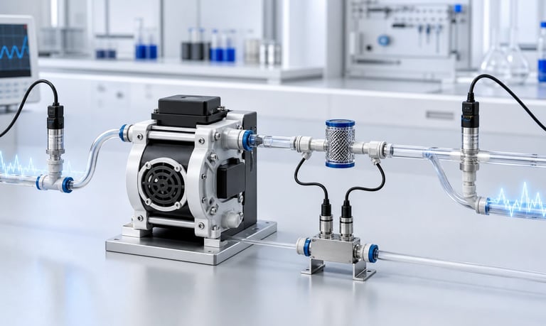
A pressure sensor for a micro pump system must use the correct gauge, absolute, or differential reference, cover normal and transient pressure without losing useful resolution, respond appropriately to pump pulsation, tolerate fluid and cleaning exposure, and remain accurate through temperature, orientation, overload, installation, and production variation.
How to Select a Pressure Sensor for a Micro Pump System
A pressure sensor can reveal inlet restriction, outlet blockage, filter loading, pump pulsation, failed priming, leaks, valve behavior, and changing system resistance. It can also support closed-loop pressure control or protect a pump and fluid path from abnormal load.
The wrong sensor can create misleading data. A gauge sensor may be unsuitable for an absolute-vacuum requirement. A wide-range sensor may survive pressure peaks but lack useful resolution. A narrow port or trapped bubble can alter the pressure waveform.
Selection should connect the pressure reference, range, accuracy, response, overload, wetted materials, ports, installation, calibration, and fault behavior to the exact pump and fluid path.
Define What the Pressure Measurement Must Do
Start with the decision the system will make from pressure.
Possible objectives include:
Detect a blocked outlet
Detect a restricted inlet
Monitor filter differential pressure
Confirm prime
Control outlet pressure
Measure vacuum in a gas or liquid system
Detect valve opening or closure
Characterize pump pulsation
Protect tubing, sensors, and fittings
Diagnose leakage or loss of suction
Define whether the sensor supports control, monitoring, service diagnostics, product safety, or a user display.
State the required detection time, threshold, accuracy, and safe response. A blockage detector may need to capture a fast pressure rise, while a filter monitor may only need a stable average.
Also define what happens if the sensor reads high, low, frozen, disconnected, or plausible but wrong.
Choose Gauge, Absolute, or Differential Pressure
Pressure reference is the first selection decision.
Gauge Pressure
Gauge pressure is referenced to local atmospheric pressure. A vented gauge sensor typically uses a reference port or vent to follow atmosphere.
It is useful for outlet pressure above ambient and vacuum below ambient when local atmosphere is the relevant reference.
Absolute Pressure
Absolute pressure is referenced to a sealed vacuum. It is useful for vacuum processes, gas sampling, altitude-independent chamber measurements, and calculations requiring true gas pressure.
Differential Pressure
A differential sensor measures pressure between two ports. It can monitor a filter, flow restriction, pump differential, or two chambers directly.
Choose based on the physical requirement. A gauge-vacuum reading changes with atmospheric pressure; an absolute reading does not use local atmosphere as zero.
Label every recorded value and software variable with reference and units.
Define Normal, Transient, and Fault Ranges
List the full pressure envelope, not only the nominal point.
Include:
Startup and priming
Normal steady operation
Pump pulsation peaks
Speed changes
Valve opening and closing
Filter loading
Outlet blockage
Inlet blockage
Siphoning or static head
Reverse pressure
Cleaning and service
Transport or sealed-volume temperature change
Select a range that covers approved transients and faults without sacrificing too much resolution during normal operation.
A sensor operating near its maximum range may clip peaks. A sensor with a much wider range may have an error or noise floor too large for low-pressure detection.
Use separate sensors or ranges when inlet vacuum and high outlet pressure cannot be measured well by one device.
Do not expose the sensor to a fault beyond its proof or burst limits merely because the display range is exceeded.
Distinguish Operating, Proof, and Burst Pressure
Operating range is the pressure over which the sensor is intended to meet its measurement specification.
Proof pressure is a temporary overload the sensor can withstand under defined conditions without permanent performance loss.
Burst pressure is a structural failure threshold or limit and is not an operating or routine test point.
Ask:
Does proof apply in both directions?
What temperature and fluid apply?
What is the maximum common-mode pressure for a differential sensor?
Can one port be overloaded while the other is vented?
Does vacuum affect a positive-pressure sensor?
How many pressure cycles were considered?
Stay within supplier-approved limits. Provide pressure relief, current limiting, timeout, valve control, or another protection if the pump can exceed them.
After an overload, verify zero and calibration before trusting the sensor.
Calculate the Required Resolution and Accuracy
Convert sensor error into the units and thresholds that matter to the application.
Review:
Accuracy as percentage of reading or full scale
Zero offset
Repeatability
Linearity
Hysteresis
Temperature coefficient
Long-term drift
Supply sensitivity
Orientation effect
Noise and digital resolution
A high-resolution digital output does not guarantee matching physical accuracy.
For a fault threshold, include process variation, pump variation, sensor tolerance, temperature, and installation. The threshold must separate normal high load from an actual blockage with sufficient margin.
For closed-loop pressure control, the sensor uncertainty contributes directly to the controlled result.
Build an error budget using the final range, fluid, temperature, pressure reference, and calibration method.
Select the Measurement Principle and Package
Miniature pressure sensors may use piezoresistive, capacitive, strain-gauge, resonant, thermal, optical, or other technologies, often behind an isolation diaphragm.
The package may be:
Board-mounted with a pressure port
Threaded or manifold-mounted
Inline with tube fittings
Flush diaphragm
Media-isolated module
Dual-port differential device
Compare the complete sensor, not only the sensing element.
Package choice affects dead volume, trapped gas, chemical exposure, port strength, sealing, assembly, and service.
A board-level sensor may simplify electronics but expose the circuit board if fluid reaches the port. A media-isolated sensor can expand material options but may add volume, compliance, and temperature behavior.
Use supplier data and application testing for the exact package.
Check Dynamic Response and Bandwidth
Pressure in a positive-displacement pump system changes cyclically. Sensor bandwidth determines whether it reports peaks, average pressure, or a filtered version.
Define the required measurement:
Steady average
Peak pressure
Peak-to-peak pulsation
Valve event
Blockage rise time
Pressure decay
Control feedback
Ask for sensor response time, mechanical resonance, internal filtering, update rate, and communication delay.
A slow sensor can miss damaging peaks. A fast sensor with a low sampling rate can alias high-frequency pulsation into a false slow signal.
Use a sampling rate and anti-alias strategy appropriate to pump speed and roller, diaphragm, or piston events.
Retain unfiltered data during development. Filtering the display does not reduce physical pressure.
Account for Pressure Pulsation
Peristaltic and diaphragm pumps produce repeated pressure pulses. Tubing compliance, trapped gas, valves, filters, dampers, sensors, and nozzles shape the waveform.
Pulsation can cause:
Sensor output oscillation
Higher peak load than average
Fatigue at ports and diaphragms
Control-loop instability
Noisy fault detection
Resonance in tubing or brackets
Measure pressure near the pump and at the protected component. The waveform can change along the fluid path.
If a snubber, restrictor, capillary, or digital filter is used, document its effect on both amplitude and response time. A blockage may occur faster than a damped measurement can respond.
Do not size the sensor only from the average gauge reading.
Minimize Measurement-Line Distortion
A sensor connected through a long narrow tube may not see the true port pressure.
The impulse line adds:
Flow resistance
Compliant volume
Delay
Resonance
Bubble traps
Temperature exposure
Leakage opportunities
For dynamic measurements, place the sensor close to the point of interest with a short, adequately sized connection.
For hot, corrosive, or contamination-sensitive fluids, a remote sensor or isolation line may be necessary, but its transfer behavior must be characterized.
Avoid side branches with dead ends that trap gas or residue. Mount pressure taps so they do not collect particles or create an uncleanable pocket.
Document tap diameter, length, orientation, and position in the production drawing.
Evaluate Port Size and Added Restriction
A pressure sensor usually draws little continuous flow, but its port, manifold, or inline package can still restrict the main path.
Check:
Through-bore diameter
Pressure tap geometry
Fittings and adapters
Protective screens
Isolation membranes
Dead volume
Flow disturbance
An inline sensor body may have a passage smaller than the tubing. This can increase pressure loss, trap particles, and alter pump pulsation.
A small side port can clog or delay pressure transmission.
Measure system flow and pressure before and after adding the sensor assembly. Include clean and fouled conditions.
Do not assume a sensor is nonintrusive because it measures pressure rather than flow.
Account for Bubbles and Trapped Gas
Gas in a liquid pressure line adds compliance and changes response. A trapped bubble can filter sharp peaks, delay pressure buildup, and release stored liquid after stop.
Bubble effects depend on:
Gas volume
Absolute pressure
Temperature
Sensor orientation
Port geometry
Fluid surface tension
Pump pulsation
A development sensor may appear stable because a bubble is damping it, then become noisier after the system is fully primed.
Orient liquid pressure ports to clear gas where possible. Define the prime procedure and inspect high points.
If a deliberate gas-separated diaphragm is part of the sensor, use the manufacturer's validated transfer design rather than an uncontrolled air pocket.
Test dry, partially primed, and bubble-free states so the system does not depend on accidental gas volume.
Account for Viscosity and Particles
Static pressure itself is not viscosity-dependent, but transmission through narrow ports and lines can become slower with viscous fluid.
Particles, fibers, crystals, or residue can block a pressure tap or coat an isolation diaphragm.
Review:
Port and passage size
Flush or recessed diaphragm
Protective filter
Orientation
Cleaning access
Temperature and viscosity range
Settling and idle behavior
A protective filter can reduce contamination but add response delay and loading.
Test step response with the actual fluid at minimum temperature and maximum viscosity.
For suspensions, compare sensor output before and after representative fouling and cleaning. A blocked tap may hold an old plausible pressure rather than report an obvious fault.
Use process plausibility checks and supporting flow or current data where risk requires it.
Review Wetted Materials
Identify every material contacting product, cleaner, rinse, vapor, and mixed waste:
Isolation diaphragm
Port and housing
O-rings and seals
Adhesives and coatings
Gel or fill fluid behind a diaphragm
Fittings and manifold
Protective screen
Evaluate exact grades for concentration, temperature, pressure, time, and cleaning.
Possible problems include:
Swelling and seal leakage
Corrosion
Stress cracking
Diaphragm embrittlement or softening
Permeation
Extractables
Adsorption
Fill-fluid contamination after rupture
Static chemical resistance does not prove sensor calibration or fatigue stability. Test zero, span, leakage, response, and structural condition after representative exposure.
If diaphragm failure can release fill fluid into the product, include that failure in the contamination and risk assessment.
Account for Temperature
Temperature affects the sensor element, electronics, isolation diaphragm, fill fluid, seals, and zero or span.
Record:
Fluid temperature
Sensor-body temperature
Ambient and enclosure temperature
Temperature transitions
Warm-up time
Cleaning temperature
Compensation may use an internal temperature that lags the fluid. A hot pulse can create temporary error before the package stabilizes.
Pressure in a sealed trapped liquid volume can also rise as temperature changes, even when the pump is off.
Test cold startup, warm steady operation, and transitions. Do not rely only on a compensated accuracy number without its temperature range and pressure conditions.
Place the sensor away from local heat sources where possible, or validate the actual thermal environment.
Consider Altitude and Atmospheric Reference
Gauge sensors reference local atmosphere. At high altitude, the same absolute pressure produces a different gauge reading.
Vented gauge sensors require a clean reference path. A blocked vent, wet membrane, sealed enclosure, or pressure difference across the product housing can shift the output.
Absolute sensors can support altitude-independent vacuum measurements, but the system may still need local atmospheric pressure for gauge calculations or suction-force estimates.
Record local atmospheric pressure during testing. Verify software conversions, sign conventions, and thresholds across the installation range.
Do not calibrate a gauge-vacuum threshold at one altitude and assume it represents the same absolute process condition everywhere.
For gas systems, pressure also affects actual and standardized flow interpretation.
Choose the Sensor Location
Place the sensor where it measures the condition that matters.
Possible locations include:
Pump inlet
Pump outlet
Before or after a filter
Near a nozzle
At a chamber
Across a valve or restriction
At a manifold branch
An inlet sensor can detect suction restriction, vent blockage, and prime loss. An outlet sensor can detect blockage and process load.
A remote chamber sensor may not reveal pressure loss in the line between chamber and pump.
For filter monitoring, use differential pressure directly or two well-matched sensors and account for their combined error.
Consider accessibility, cleaning, bubble clearance, vibration, cable routing, and failure containment.
The correct location for control may differ from the correct location for pump protection.
Review Electrical and Communication Interfaces
Pressure sensors may provide analog voltage, current, frequency, digital communication, or a discrete switch output.
Check:
Supply voltage and current
Output range and reference
Ratiometric behavior
Input impedance
Resolution and update rate
Ground and shielding
Connector and pinout
Cable length
Startup time
Diagnostics and error codes
Communication loss behavior
Pump motors and drivers can create electrical noise. Route sensitive analog signals away from high-current switching loops and verify electromagnetic compatibility in the final product.
Define software handling for out-of-range, short circuit, open circuit, stale data, invalid status, and reset.
A valid-looking frozen reading requires timestamps, plausibility checks, or independent process evidence to detect.
Plan Calibration and Verification
Ask how the sensor was factory calibrated:
Pressure reference
Medium
Temperature
Orientation
Number of points
Reference equipment
Uncertainty
Coefficient storage
Verify the installed sensor with a suitable pressure standard across the required range. Include vacuum and positive pressure if both are used.
Use multiple points on increasing and decreasing pressure to observe hysteresis. Verify zero after installation because mounting stress can shift it.
For differential sensors, check both directions where applicable and common-mode pressure.
Do not calibrate out a blocked port, trapped bubble, leaking fitting, or unstable pressure source.
Define recalibration or verification triggers after overload, cleaning, sensor replacement, long service, failed plausibility, or a design change.
Use Pressure for Fault Detection Carefully
Pressure can identify abnormal resistance but usually needs context.
Examples:
High outlet pressure with low flow suggests blockage
High inlet vacuum suggests inlet restriction
Low pressure and low flow may indicate empty source, leak, or failed pump
Slow pressure decay may indicate leakage or compliant volume
Repeating peaks can show valve or roller behavior
Combine pressure with flow, motor current, speed, valve state, reservoir level, and temperature.
Set thresholds from normal variation across fluid, pressure, voltage, pump samples, and temperature. Include persistence time to avoid false faults from normal pulsation.
Define response: stop, close a valve, reverse, alarm, limit speed, or enter service mode.
Test real faults. A model based on one prototype may not cover production variation or aged components.
Integrate Closed-Loop Pressure Control
A pressure-control loop includes pump response, sensor delay, fluid compliance, pulsation, valve behavior, filtering, motor acceleration, and controller tuning.
High loop gain may chase pump pulses and create speed oscillation. Excess filtering can delay response to blockage.
Define:
Setpoint and allowed error
Control bandwidth
Minimum and maximum pump command
Pressure ramp
Overshoot limit
Integral windup behavior
Valve coordination
Fault timeout
Use mechanical and fluidic measures to reduce high-frequency pulsation where necessary. Control average or lower-frequency pressure changes within the system bandwidth.
Test setpoint changes, changing flow resistance, leakage, empty source, blocked outlet, sensor disconnect, frozen reading, and power recovery.
Do not allow a low failed reading to command unlimited pump output.
Validate Mechanical Integration
Pressure ports and sensor bodies must withstand tube pull, fitting torque, vibration, shock, and mounting stress.
Check:
Port insertion depth
Thread and sealant
O-ring or gasket
Tube clamps
Manifold flatness and torque
Board strain
Heavy attached components
Pump vibration
Service access
A board-mounted port should not support a heavy valve, filter, or long stiff tube without suitable mechanical support.
Mounting screws can distort a package or manifold and shift zero. Follow the supplier torque and sealing method.
After vibration, transport, thermal cycling, and service, repeat leak, zero, span, and response tests.
Contain fluid if a port or diaphragm failure could damage electronics or create a hazard.
Build a Representative Pressure-Sensor Test
Use the actual pump, fluid, tubing, fittings, valves, filters, electronics, software, orientation, and enclosure.
Record:
Reference and sensor pressure
Pressure reference and units
Pump speed, current, flow, and voltage
Fluid and sensor temperature
Pulsation waveform and peak pressure
Response and delay
Zero and drift
Bubbles and priming state
Fault and overload behavior
Leakage and pressure decay
Test minimum, normal, maximum, startup, shutdown, clean, loaded, and approved fault conditions.
Include multiple pump and sensor samples, fluid viscosity and temperature extremes, altitude range, aging, cleaning, and production assembly variation.
Preserve unfiltered raw data and document all processing.
Pressure-Sensor Selection Checklist
Measurement objective and fault response defined
Gauge, absolute, or differential reference selected correctly
Normal, transient, reverse, cleaning, and fault ranges mapped
Operating, proof, burst, and common-mode limits distinguished
Accuracy, repeatability, resolution, noise, and drift budgeted
Sensor principle and package matched to fluid and installation
Bandwidth, update rate, filtering, and aliasing evaluated
Pulsation peaks measured at relevant locations
Pressure tap and impulse-line distortion minimized
Port size, dead volume, restriction, and fouling reviewed
Bubble trapping and priming state tested
Viscosity, particles, and cleaning effects included
Complete wetted materials and isolation fill fluid reviewed
Temperature transitions and compensation verified
Altitude, atmospheric reference, and venting evaluated
Sensor location chosen for control and protection objectives
Electrical interface, noise, diagnostics, and stale data handled
Calibration, hysteresis, installation zero, and triggers documented
Fault thresholds validated with supporting signals
Closed-loop control and mechanical integration tested
Common Pressure-Sensor Mistakes
Using gauge pressure for an absolute-vacuum requirement
Recording pressure without reference or units
Selecting range only from normal average pressure
Ignoring pump pulsation peaks
Treating proof or burst pressure as an operating rating
Choosing a wide range with inadequate low-pressure resolution
Connecting through a long narrow tube without response testing
Allowing bubbles to damp or delay the measurement unpredictably
Ignoring a clogged pressure tap
Checking chemical resistance but not isolation-diaphragm behavior
Calibrating at one temperature and orientation only
Using a vented gauge sensor with a blocked reference
Tuning control to chase every pump pulse
Relying on pressure alone to identify every fault
Supporting heavy components through a small sensor port
Frequently Asked Questions
Should a micro pump use a gauge or absolute pressure sensor?
Use gauge sensing when local atmosphere is the relevant reference and absolute sensing when true pressure relative to vacuum matters. Differential sensing is useful across filters or restrictions.
Why does a pressure sensor show strong pump pulsation?
It may be measuring real cyclic pressure from the pump. Sensor bandwidth, tap geometry, bubbles, tubing compliance, sampling, and aliasing also affect the waveform.
Can one sensor measure both inlet vacuum and outlet pressure?
Only if its bidirectional range, accuracy, proof limits, pressure reference, ports, and resolution support both. Separate sensors often provide better placement and resolution.
Where should an outlet pressure sensor be installed?
Place it near the component or pump condition that must be protected, while minimizing tap delay, trapped gas, dead volume, vibration, and service difficulty.
Can pressure be used to detect an empty reservoir?
It can contribute, but empty source, inlet leak, vent blockage, bubbles, and pump wear can create overlapping signals. Combine pressure with flow, level, current, or other evidence.
How should a pressure sensor be calibrated after installation?
Use a traceable reference across multiple increasing and decreasing points under representative temperature and orientation. Verify zero after mounting and define recalibration triggers.
Kamoer Pressure-Sensor Integration Support
Kamoer can help evaluate inlet vacuum, outlet pressure, pulsation, sensor range, placement, ports, fluid properties, control, fault detection, and representative pressure-sensor tests for OEM micro pump systems.
Related Stories
Kamoer Fluid Tech (Shanghai) Co., Ltd.
pump@kamoer.com