

How to Select a Flow Sensor for a Micro Pump System
PUMP SELECTION GUIDES
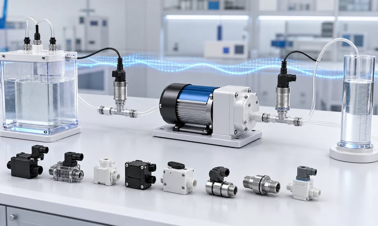
A flow sensor for a micro pump system must measure the required liquid or gas range with suitable accuracy, repeatability, response, and output while adding acceptable pressure loss and remaining stable with pump pulsation, bubbles, viscosity, temperature, pressure, wetted materials, cleaning, orientation, and calibration conditions.
How to Select a Flow Sensor for a Micro Pump System
A flow sensor can verify that a micro pump is moving fluid, support closed-loop control, detect empty reservoirs or blockage, document a sample volume, and improve dosing confidence. The sensor also becomes part of the fluid path and can change the behavior it is intended to measure.
A sensor with narrow passages may add inlet vacuum or outlet pressure. A fast sensor may reveal normal pump pulsation that a slow display hides. Bubbles, viscosity, temperature, particles, orientation, and fluid properties can create errors or unstable readings.
Selection should begin with the physical measurement requirement and the complete pump operating range, not only a nominal flow value or digital interface.
Define What the Flow Measurement Must Accomplish
Different objectives require different sensor performance.
Possible objectives include:
Confirm flow is present
Measure average transfer flow
Measure an individual dose
Detect an empty source
Detect blockage or a leak
Regulate closed-loop flow
Record gas sample volume
Monitor filter loading
Verify a cleaning sequence
Detect pump degradation
Define whether the system needs absolute accuracy, repeatable trend, fast fault detection, or only a binary flow indication.
Also define the decision the controller will make from the measurement. A sensor used for billing, analytical volume, safety shutdown, or process control may require a different validation approach from one used for a user display.
State what happens if the sensor fails, drifts, becomes blocked, traps a bubble, or reports a plausible value with no real flow.
Define the Flow Range and Units
Specify minimum, typical, maximum, prime, purge, cleaning, and fault flows. Include reverse flow if the pump can reverse.
For liquids, clarify whether flow is volumetric or mass-based. Fluid density matters when converting between them.
For gases, identify whether flow is:
Actual volumetric flow
Standardized or normalized volumetric flow
Mass flow
Standard and normal conditions require defined reference pressure and temperature.
Do not select a sensor whose full-scale range is far above the normal operating point merely because it covers a short prime mode. Resolution and accuracy may be inadequate during dosing.
One sensor may not cover very low dose flow and high purge flow with equal quality. Consider separate modes, a bypass, two ranges, or a different measurement architecture when the required span is too wide.
Distinguish Accuracy, Repeatability, and Resolution
Accuracy describes closeness to the true value under specified conditions. Repeatability describes spread when the same measurement is repeated. Resolution is the smallest displayed or reported change.
A sensor can have fine digital resolution without corresponding physical accuracy. Filtering can create stable-looking output while the underlying measurement is biased.
Ask how the supplier specifies:
Error as a percentage of reading or full scale
Zero offset
Repeatability
Linearity
Hysteresis
Temperature effect
Pressure effect
Orientation effect
Long-term drift
At low flow, a full-scale error term can dominate. Calculate the error in the same units as the minimum required dose or flow.
Build an error budget that includes the reference standard, fluid properties, installation, tubing compliance, sampling, conversion, and controller timing.
Select a Suitable Measurement Principle
Miniature flow sensors may use thermal, differential-pressure, ultrasonic, Coriolis, positive-displacement, turbine, optical, electromagnetic, calorimetric, or other principles.
Each has different dependencies.
Thermal sensors can be compact and sensitive but may depend on fluid thermal properties, temperature, gas composition, bubbles, and fouling.
Differential-pressure sensors infer flow from pressure loss across a restriction. They depend on viscosity, density, geometry, temperature, and flow regime and add intentional resistance.
Mechanical sensors may provide direct motion or displaced volume but introduce moving parts, inertia, wear, pressure loss, and particle sensitivity.
Ultrasonic or other nonintrusive approaches can reduce wetted obstruction but depend on tube geometry, fluid acoustic properties, bubbles, and installation.
Do not select from technology labels alone. Compare the exact sensor with the actual fluid, range, response, pressure, and cleaning process.
Check Pressure Loss
The sensor is a restriction. Its pressure loss can reduce pump flow and change the operating point.
Pressure loss depends on:
Flow
Internal passage
Fluid viscosity and density
Temperature
Particles and fouling
Flow direction
Gas or liquid phase
Ask for a pressure-loss curve with stated fluid and temperature. Measure it in the production system.
An inlet-mounted sensor can increase vacuum, slow priming, cause incomplete tube or chamber refill, draw air through marginal connections, or promote outgassing.
An outlet-mounted sensor can increase back pressure, motor load, heat, tubing expansion, pulsation, and post-stop delivery.
Do not treat the sensor as a passive observer. Include its clean and fouled pressure loss in the pump selection and fault analysis.
Decide Where to Install the Sensor
Placement determines what the sensor measures and how it affects the pump.
Possible locations include:
Upstream of the pump
Immediately downstream
After a filter or valve
Near the final dispensing point
In a bypass or return line
At a branch in a manifold
Upstream placement may detect source flow but adds suction-side restriction. Downstream placement measures delivered pump output more directly but may see stronger pulsation and pressure.
A sensor near the nozzle includes downstream leakage and valve effects but may be harder to service. A sensor near the pump can miss liquid stored or released in a long compliant outlet line.
Consider pressure, bubbles, temperature, vibration, accessibility, cleaning, dead volume, and cable routing.
Use the supplier's required upstream and downstream geometry where practical and verify the final layout.
Understand Pump Pulsation
Peristaltic, diaphragm, piston, and other positive-displacement pumps produce cyclic flow. Instantaneous flow may rise, fall, or briefly reverse while average flow remains stable.
A fast sensor can show the waveform. A slow sensor may average it mechanically or electronically.
Define whether the application needs:
Instantaneous flow
Peak flow
Peak-to-peak pulsation
Average over a pump cycle
Totalized volume
Dose endpoint
The sensor bandwidth and sampling rate must support the selected quantity. A low sampling rate can alias pump pulses into a false slow fluctuation.
Filtering changes the displayed signal but not the physical flow. Retain unfiltered data when analyzing pulsation or pressure peaks.
If the sensor output drives a controller, tune the loop so it does not chase each mechanical pulse and create speed oscillation.
Evaluate Response Time and Delay
Response time includes sensor physics, fluid transport, internal filtering, digital processing, communication, and controller sampling.
For short doses, the sensor may respond after much of the liquid has already passed. A long outlet tube adds transport delay between pump motion and sensing.
Ask for:
Sensor response definition
Rise and fall time
Internal averaging
Update rate
Communication latency
Startup and zeroing time
Behavior after range changes
Measure total system delay from pump command to sensor response and from sensor threshold to pump stop.
Closed-loop dose overshoot depends on fluid stored between pump and sensor, pressure, valve timing, motor deceleration, and processing delay.
Do not assume a high data-output rate means a fast physical measurement.
Account for Bubbles
Bubbles can disrupt many flow-sensing principles. They may appear as spikes, dropouts, false flow, or a lower liquid fraction.
Review:
Bubble sensitivity
Maximum gas segment the sensor can pass
Internal high points
Orientation
Priming and venting
Wetted surface behavior
Recovery after a bubble
A sensor may report total gas-liquid movement while the process needs liquid volume only.
Place and orient the sensor to avoid trapping gas. Correct inlet leaks, reservoir vortexing, outgassing, and incomplete prime before relying on software filtering.
If bubbles are unavoidable, test known gas fractions and define detection or recovery. An optical bubble detector may complement a flow sensor, but it also requires validated limits.
Do not recalibrate a sensor over a changing bubble condition.
Account for Viscosity and Density
Sensor calibration may depend on fluid viscosity and density. The effect varies by measurement principle.
Differential-pressure sensors are strongly linked to viscosity and flow regime. Mechanical sensors experience drag and inertia changes. Thermal sensors depend on heat-transfer properties. Mass and volumetric sensors report different quantities.
Record:
Fluid identity and lot
Density and reference temperature
Viscosity and measurement method
Non-Newtonian behavior
Concentration range
Temperature range
Do not use a water calibration for a viscous liquid without supplier evidence or system validation.
If the fluid changes between product, cleaner, rinse, and calibration solution, the sensor may need separate coefficients or a mode-specific interpretation.
For mixtures whose concentration changes, one fixed property value may create systematic error.
Account for Temperature
Temperature affects fluid properties, sensor electronics, wetted materials, zero offset, and calibration.
Ask whether compensation uses:
Sensor-body temperature
Fluid temperature
A fixed model
User-entered properties
Factory calibration
The sensor body may not reach fluid temperature immediately. During startup or a hot cleaning pulse, compensation can lag.
Measure fluid temperature near the sensor and compare cold startup, warm steady operation, and temperature transitions.
If a sensor warms the fluid, as some thermal principles can, assess whether the heat affects the process or tiny dose.
Validate the full operating and storage range. Do not infer compatibility or accuracy from one room-temperature specification.
Check Pressure and Structural Limits
Verify maximum operating pressure, proof pressure, burst limit, vacuum capability, and differential pressure under stated temperature and fluid conditions.
The sensor may see:
Pump pulsation peaks
Outlet blockage
Valve switching
Siphon pressure
Reverse pressure
Vacuum during drain or suction
Cleaning pressure
Flexible tubing or dampers can store pressure and continue loading the sensor after the pump stops.
A sensor designed for positive pressure may trap gas or deform under vacuum. A differential device may have limits on common-mode pressure and one-sided overload.
Use suitable relief, current limit, timeout, or fault control if the pump can exceed sensor limits.
Capture transient pressure with adequate bandwidth rather than relying only on a slow gauge.
Review Wetted Materials and Purity
List sensor-body materials, seals, coatings, adhesives, membranes, heaters, electrodes, windows, and fittings exposed to fluid.
Evaluate product, cleaner, rinse, calibration fluid, vapor, and mixed waste at actual concentration, temperature, pressure, and time.
Potential issues include:
Swelling and leakage
Corrosion
Stress cracking
Coating damage
Adsorption
Extractables
Permeation
Fouling
Changed optical or thermal response
The sensor may have a large surface-to-volume ratio relative to a small dose. Adsorption or carryover can be significant.
Static compatibility supports screening but does not prove calibration stability or cleanability. Test the complete sensor after repeated exposure and cleaning.
Do not infer food, medical, or regulatory suitability from one material name.
Evaluate Particles and Fouling
Particles, fibers, crystals, biological material, oils, and dried residue can block passages or change the sensing surface.
Check:
Minimum internal passage
Flow restriction geometry
Surface finish
Particle tolerance
Cleaning access
Signal change with fouling
Pressure-loss change
A filter can protect the sensor but adds pressure loss and may remove desired material. Place it based on the contamination source and process requirement.
Test clean, realistically fouled, and post-clean conditions. Record zero, sensitivity, flow, and pressure loss.
If fouling creates a plausible but biased signal, the controller may not detect the fault. Consider pressure, current, redundant measurement, periodic reference checks, or process plausibility limits.
Check Bidirectional and Zero-Flow Behavior
Some systems reverse the pump or experience backflow after stop. Confirm whether the sensor measures both directions, clips negative flow, or reports an error.
At zero flow, review:
Zero offset
Noise
Auto-zero behavior
Drift
Pressure-dependent output
Thermal convection
Vibration sensitivity
Siphon or leakage detection
An automatic zero routine can create error if liquid is still moving during calibration. A check valve or compliant tube may release stored fluid after the motor stops.
Define the conditions required for a valid zero and how the controller verifies them.
If reverse flow is unacceptable, the sensor can help detect it only if its direction and low-flow performance are validated.
Review Electrical and Communication Interfaces
The sensor output must integrate with the OEM electronics and software.
Possible interfaces include:
Analog voltage or current
Frequency or pulse
Digital serial communication
I2C, SPI, UART, CAN, or another protocol
Discrete flow switch
Check:
Supply voltage and current
Ground reference
Output range and scaling
Resolution and update rate
Connector and pinout
Cable length and shielding
Startup time
Error codes and diagnostics
Addressing and bus behavior
Electromagnetic compatibility
Define behavior during brownout, disconnection, communication loss, invalid data, and firmware reset.
A frozen valid-looking value can be more dangerous than an obvious error. Use timestamps, plausibility checks, watchdogs, or redundant signals where risk requires it.
Plan Calibration and Verification
Factory calibration may use water, air, a reference gas, or another fluid under defined pressure and temperature. Determine how closely it represents the application.
Ask for:
Calibration medium
Flow range and points
Pressure and temperature
Reference standard
Orientation
Uncertainty
Traceability
Coefficient storage
Recalibration guidance
Verify the installed sensor using a suitable gravimetric, volumetric, mass-flow, or reference method.
For liquid volume, control density, evaporation, and collection timing. For gas, define actual or standard flow and reference conditions.
Use multiple points and independent verification data. Do not adjust a sensor to match one unstable pump reading.
Define recalibration triggers after cleaning, fluid change, sensor replacement, drift, storage, or a failed verification.
Integrate Closed-Loop Control Carefully
Closed-loop flow control can compensate for pressure, voltage, tube wear, or viscosity changes within the validated range.
The loop includes:
Pump response
Fluid compliance
Sensor delay
Filtering
Communication
Controller gains
Motor acceleration
Valve and nozzle behavior
If bandwidth is too high, the controller may chase pump pulsation. If too low, it may not correct a short dose or sudden restriction.
Use mechanical and fluid-path measures for high-frequency ripple, then control average or lower-frequency variation.
Set limits for maximum pump command, run time, pressure, current, and dose. A failed low sensor reading should not drive the pump indefinitely.
Test startup, step changes, disturbance rejection, overshoot, settling, bubbles, blockage, empty source, sensor disconnection, and frozen output.
Validate Totalized Volume and Dosing
Flow integrated over time can estimate delivered volume:
Delivered volume = integral of flow over time
In practice, error comes from zero offset, response delay, sampling, filtering, pulse timing, bubbles, density, calibration, and flow outside the sensor range.
For discrete doses, compare sensor total with independent mass or volume measurements. Include:
Minimum and maximum dose
First dose after idle
Acceleration and stopping
Reverse or suck-back motion
Post-stop dripping
Pressure and temperature extremes
Define when integration starts and stops. Fluid may continue moving after the motor command ends.
Avoid resetting the totalizer before delayed sensor data have arrived. Synchronize clocks where pump and sensor data come from different controllers.
Build Fault Detection from Multiple Signals
Flow data can support diagnosis, but one value rarely identifies the exact fault.
Combine as appropriate:
Flow
Inlet and outlet pressure
Motor current and speed
Reservoir level
Bubble detection
Valve state
Temperature
Commanded dose
For example, low flow with high outlet pressure suggests restriction, while low flow with low current and low reservoir level may suggest an empty source. Air leaks can create variable flow with bubbles and rising inlet vacuum.
Define fault thresholds, persistence time, and safe response. Natural pulsation should not trigger repeated false alarms.
Validate every diagnostic with real faults and production variation. A current or flow model created from one pump may not cover all units and fluid conditions.
Build a Representative Sensor Test
Use the actual pump, fluid, tubing, fittings, valves, filters, pressure, temperature, orientation, electronics, and software.
Record:
Reference and sensor flow
Zero and drift
Inlet and outlet pressure
Pump speed and current
Fluid and sensor temperature
Response and delay
Pulsation waveform
Bubbles and priming
Reverse and post-stop flow
Signal and communication faults
Test minimum, typical, maximum, prime, purge, and cleaning modes. Include new and aged pumps, filters, tubing, and sensor samples.
Evaluate clean and fouled conditions. Verify calibration after chemical and thermal exposure.
Preserve raw unfiltered data and all processing settings.
Flow-Sensor Selection Checklist
Measurement objective and controller action defined
Liquid or gas flow basis and units identified
Minimum, normal, maximum, prime, purge, and reverse flows included
Accuracy, repeatability, resolution, and uncertainty separated
Measurement principle matched to fluid and process
Clean and fouled pressure loss included in pump load
Sensor location selected from what must be measured
Pulsation bandwidth, sampling, filtering, and aliasing evaluated
Physical response, communication delay, and dose overshoot measured
Bubble sensitivity, venting, and recovery tested
Viscosity, density, temperature, and fluid variation included
Pressure, vacuum, and transient structural limits verified
Complete wetted materials and product purity reviewed
Particles, fouling, adsorption, and cleaning evaluated
Bidirectional and zero-flow behavior defined
Electrical interface, startup, errors, and frozen data handled
Calibration method, reference, coefficients, and triggers documented
Closed-loop tuning and safety limits validated
Totalized volume checked against an independent reference
Fault detection uses sufficient supporting signals
Common Flow-Sensor Mistakes
Selecting from nominal flow range only
Treating display resolution as measurement accuracy
Ignoring sensor pressure loss
Mounting a restrictive sensor on the pump inlet without vacuum testing
Filtering away pulsation without understanding it
Sampling too slowly and creating aliasing
Using water calibration for a viscous fluid
Ignoring bubbles and mixed gas-liquid flow
Assuming a high update rate means fast physical response
Treating standardized gas flow as actual volumetric flow
Checking material compatibility but not fouling or adsorption
Auto-zeroing while fluid is still moving
Tuning the controller to chase each pump pulse
Using flow alone to identify every fault
Validating one sensor and one pump sample
Frequently Asked Questions
Where should a flow sensor be placed in a micro pump system?
Place it where it measures the quantity that matters while keeping pressure loss, bubbles, temperature, service, and downstream stored volume acceptable. Compare upstream and downstream options.
Why does a flow sensor fluctuate with a peristaltic pump?
The sensor may be measuring real roller pulsation. Sensor bandwidth, sampling, aliasing, bubbles, and installation can also affect the waveform.
Can a flow sensor improve dosing accuracy?
It can support feedback or totalized volume, but accuracy still depends on calibration, response delay, bubbles, pressure, fluid properties, pump stopping, and downstream dripping.
Does a flow sensor reduce pump flow?
It may. Internal passages create pressure loss. On the inlet this increases vacuum; on the outlet it increases back pressure. Measure the complete operating range.
Can one sensor measure both liquid and gas?
Only if its measurement principle, calibration, materials, range, and supplier specifications support both. Gas and liquid have very different density, thermal, compressibility, and bubble behavior.
How should a micro pump flow sensor be calibrated?
Use a suitable reference and the actual fluid, pressure, temperature, orientation, flow range, and installation. Verify multiple points independently and define recalibration triggers.
Kamoer Flow-Sensor Integration Support
Kamoer can help evaluate pump flow, pressure, pulsation, sensor location, pressure loss, fluid properties, feedback, calibration, fault detection, and representative flow-sensor tests for OEM micro pump systems.
Related Stories
Kamoer Fluid Tech (Shanghai) Co., Ltd.
pump@kamoer.com