

How to Select a Filter for a Micro Pump System
PUMP SELECTION GUIDES
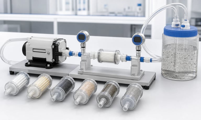
A filter for a micro pump system must remove the particles that threaten the pump or process while maintaining acceptable pressure loss from clean through loaded condition, preserving required product solids, avoiding trapped gas, matching fluid and cleaning chemistry, and supporting monitoring, replacement, and fault control.
How to Select a Filter for a Micro Pump System
A filter can protect a micro pump, valve, flow sensor, nozzle, analytical cell, or final product from unwanted particles. It can also become the largest restriction in the fluid path, especially when the filter loads with debris.
Selecting only by nominal pore size can lead to slow priming, reduced flow, high inlet vacuum, rising outlet pressure, bubbles, motor heating, collapsed tubing, unstable doses, or premature service.
The filter must be evaluated as part of the complete system. Filtration target, particle distribution, fluid viscosity, flow, clean and loaded pressure loss, location, materials, orientation, bubbles, cleaning, monitoring, and replacement all affect performance.
Define What the Filter Must Protect
Start with the failure the filter should prevent.
Possible objectives include:
Protect diaphragm-pump valves from particles
Protect a nozzle or small orifice from blockage
Protect a flow or pressure sensor
Remove manufacturing debris
Prevent crystals or agglomerates from entering the path
Control contamination in a sample
Protect a downstream process
Separate gas and liquid phases with a membrane
Define the harmful particle size, shape, hardness, concentration, and source. A filter cannot be selected meaningfully from "keep the fluid clean."
Also identify particles that must remain. A suspension, reagent, food product, cell sample, or analytical stream may contain intentional solids. Removing them can change product performance or make a sample unrepresentative.
Write an acceptance requirement for both protection and fluid quality.
Characterize the Contamination
Document the contamination challenge:
Particle-size distribution
Largest expected particle or agglomerate
Shape, fibers, flakes, and aspect ratio
Hardness and abrasiveness
Particle concentration
Total contamination load
Settling or flotation
Crystal growth
Biological or organic material
Manufacturing debris
Wear particles from tubing, valves, or pump components
The initial fluid may be clean while the system generates debris during life. Peristaltic tube wear, seal damage, fitting assembly, corrosion, and dried residue can create particles downstream of an inlet filter.
Test samples after realistic storage, mixing, temperature cycles, and idle periods. Agglomerates and crystals may be larger than the original formulation.
If the filter supports contamination control, use a particle measurement method appropriate to the size and material of concern.
Understand Nominal and Absolute Ratings
Filter ratings may be described as nominal, absolute, retention efficiency, beta ratio, or another supplier-specific measure. These terms require the test method and efficiency definition.
A nominal rating does not necessarily mean every particle larger than that value is captured. An absolute claim still requires a defined test, fluid, particle shape, and efficiency threshold.
Ask:
What test standard or method was used?
What challenge particles and fluid were used?
What retention efficiency applies?
Is the rating based on the media or complete filter?
Does deformation under pressure change the pore structure?
How does loading affect retention?
Do not compare filters only by a micron number when their rating methods differ.
For depth media, particles may be captured throughout the material. Surface membranes may have a more defined barrier but can load differently.
Select Pore Size from the Protected Component
The filter should capture particles that can damage or obstruct the most sensitive downstream feature.
Identify:
Valve-seat clearance
Nozzle or needle passage
Sensor channel
Membrane or analytical cell
Pump chamber and port geometry
Product cleanliness requirement
Use component supplier data and system tests. The smallest geometric opening is not always the only limit; fibers can bridge, soft particles can deform, and sticky residue can build up over time.
Choosing a much finer filter than necessary increases pressure loss and shortens service life without automatically improving the process.
If protection requires very fine filtration, consider a staged approach: upstream screening for large debris followed by finer filtration. Each stage still adds volume, cost, and maintenance.
Measure Clean Pressure Loss
Every filter creates resistance before it captures any contamination.
Pressure loss depends on:
Filter area
Media thickness and porosity
Pore structure
Fluid viscosity
Flow rate
Temperature
Housing passages and fittings
Gas or liquid condition
Request or measure a pressure-loss curve across the required flow range. Confirm the fluid and temperature used.
A filter that performs well with air or water may be too restrictive for viscous liquid. Pressure loss may be nonlinear with non-Newtonian fluids.
Measure pressure directly before and after the filter using sensors whose passages do not dominate the result.
Include the housing. A large media area does not help if the inlet and outlet ports are narrow.
Design for Loaded Pressure Loss
The clean condition is only the beginning. As particles accumulate, pressure loss rises and flow may fall.
Define:
Expected contamination mass or volume
Loading pattern
Maximum allowed differential pressure
Minimum acceptable flow
Replacement or cleaning point
Safety margin for variation
Behavior if the filter is ignored
Load filters with representative contamination, not only standardized test dust, when the real material is sticky, fibrous, deformable, crystalline, or biological.
Record flow and differential pressure throughout loading. A filter may block suddenly or rise gradually depending on media and particles.
Do not set the service interval only from operating time. Contamination load may vary by fluid batch, environment, process event, and upstream wear.
Use differential pressure, flow, batch count, processed volume, or another validated trigger where appropriate.
Choose Inlet or Outlet Placement
Filter location changes which components are protected and how the pump is loaded.
Inlet Filter
An inlet filter can protect the pump from reservoir debris. Its pressure loss increases inlet vacuum and can cause incomplete refill, bubbles, tube collapse, cavitation-like behavior, or failed priming.
Outlet Filter
An outlet filter can capture pump-generated particles and protect the downstream process. Its pressure loss increases outlet pressure, motor load, tube expansion, leakage risk, and stored volume.
Point-of-Use Filter
A filter near the nozzle or analytical device provides local protection but may leave a long upstream path that holds contamination. It can also affect final dose timing and post-stop dripping.
Some systems need more than one filter, but every added element creates resistance, dead volume, and service work.
Place the filter based on the contamination source and protected component, then test the resulting inlet and outlet load.
Check Pump-Type Sensitivity
Peristaltic pumps rely on tube recovery and inlet refill. A restrictive inlet filter can flatten the speed-to-flow curve, especially with viscous liquid or high speed.
An outlet filter increases pressure and can change tube expansion, occlusion slip, pulsation, motor current, and tubing life.
Diaphragm liquid pumps rely on chamber filling and check-valve response. Inlet restriction can reduce prime and flow. Outlet restriction can increase internal leakage, current, valve load, and heat.
Gas pumps are sensitive to filter pressure loss, humidity, condensation, and whether flow is measured as actual or standardized volume.
Match the filter to the pump's operating point rather than selecting it separately. Measure performance with clean and loaded filters installed.
Account for Fluid Viscosity and Temperature
Higher viscosity increases filter pressure loss. Cold fluid may be substantially more restrictive than the same formulation at room temperature.
Record:
Minimum, typical, and maximum viscosity
Temperature range
Non-Newtonian behavior
Solids concentration
Fluid aging or curing
Cleaning-fluid viscosity
If the fluid is shear-thinning or contains a yield-stress structure, flow through fine media may not follow a simple linear model.
Heating can reduce viscosity but may change product stability, chemical compatibility, evaporation, and filter-media properties.
Test cold startup and stabilized operation. A filter that passes warm steady flow may prevent the pump from priming cold.
Do not use a water-based pressure-drop value without qualification for a viscous production liquid.
Review Filter Area and Geometry
Increasing effective media area can reduce initial velocity and pressure loss and increase contamination capacity. Larger area also increases housing size, retained volume, prime time, and cost.
Review:
Flat, pleated, depth, capsule, disc, or tubular geometry
Effective area
Flow distribution
Support layers
Seal or edge-bond design
Housing passages
Orientation
Drainability
Poor flow distribution can load one region early while much of the media remains unused.
Pleats can collapse or contact under differential pressure if not supported. Depth media may hold more contamination but can retain product and cleaner.
Select geometry from pressure, loading, cleaning, volume, and service needs rather than media area alone.
Check Bubble Trapping and Priming
Filters can trap gas in media pores, pleats, housings, and high points. Hydrophobic and hydrophilic behavior affects wetting.
Trapped gas can cause:
Long prime time
Reduced liquid flow
Unstable sensor readings
Compressed volume and dose delay
Sudden bubble release
Partial use of filter area
Test dry prime, prewetted prime, wet restart, and partial drain. Define whether prewetting is required and which fluid can be used.
Orient the filter so gas can escape where its design permits. A housing with an outlet below a high internal cavity may never clear completely.
Do not puncture, vent, or modify a filter housing unless the design specifically supports it.
If a vent is included, evaluate contamination, fluid loss, vapor, maintenance, and failure behavior.
Consider Hydrophobic and Hydrophilic Membranes
Membrane wetting properties can be used to vent gas, block liquid, or pass liquid after wetting. The behavior depends on material, pore structure, fluid surface tension, pressure, temperature, and contamination.
A hydrophobic air vent may become wetted by surfactants, solvents, oils, or condensate and stop venting or allow leakage.
A hydrophilic liquid membrane may require complete wetting before flow and can trap air during startup.
Ask for:
Liquid entry or breakthrough conditions
Gas-flow performance
Wetting compatibility
Effect of cleaners and surfactants
Orientation
Drying and reuse behavior
Integrity test method
Do not treat membrane labels as universal barriers. Test the exact fluid formulation and pressure range.
Review Wetted Materials
The filter includes media, supports, housing, seals, adhesives, welds, inks, and fittings.
Evaluate exact grades against:
Product fluid
Cleaner and sanitizer
Rinse and calibration fluid
Mixed waste
Temperature
Pressure and vacuum
Exposure time
Wet-dry cycles
Possible failures include swelling, softening, hardening, stress cracking, corrosion, delamination, extraction, adsorption, permeability, and loss of seal.
Fluid can extract material from a large filter surface area or adsorb active ingredients onto it. This may be significant even when no leak occurs.
Static compatibility supports screening. Test complete filters for flow, leakage, retention, pressure resistance, and fluid purity after representative exposure.
Do not infer regulatory suitability from media material alone.
Evaluate Adsorption and Product Loss
Filter media can bind proteins, dyes, active ingredients, oils, surfactants, particles, or trace analytes.
Consequences include:
Lower delivered concentration
Delayed breakthrough
Carryover between fluids
Biased analytical samples
Color or odor retention
Reduced yield
Evaluate the first volume after a new filter, stabilized output, and release during later rinsing.
Preconditioning may reduce adsorption but consumes fluid and must be validated. A filter material described as low-binding still requires testing with the actual product and detection method.
Use mass balance or an application-specific analytical method when concentration matters. Stable pump flow does not prove chemical recovery through the filter.
Account for Particles the Process Must Keep
A filter can change a suspension by removing desired particles, cells, fibers, crystals, droplets, or agglomerates.
For sampling and dosing, measure downstream particle concentration and distribution, not only total liquid flow.
Consider:
Deformable particles passing pores
Fibers bridging across media
Agglomerates breaking or collecting
Cake formation
Preferential retention
Shear at narrow passages
If the process needs protection from rare large debris while retaining a broad desired particle population, a screen or larger-area separator may be more appropriate than a fine membrane.
Define the acceptable product change and verify it across filter life.
Do not select a filter that makes the sample cleaner but unrepresentative.
Check Pressure and Structural Limits
Filters experience differential pressure, not only system gauge pressure. A blocked filter can see nearly the full pump pressure across its media or housing.
Verify:
Maximum forward differential pressure
Reverse differential pressure
Burst or structural limit
Vacuum collapse resistance
Temperature derating
Pressure pulses
Wet and dry condition
Chemical exposure
End-of-life loading
An inlet filter housing may collapse under vacuum even when it withstands positive pressure. A membrane may deform, bypass, or change pore behavior under differential load.
Stay within supplier-approved conditions. If a pump can exceed the filter limit during blockage, provide pressure relief, current limit, timeout, detection, or another protection.
Test connections and seals along with the media.
Measure Pulsation Effects
Pulsating flow creates cyclic differential pressure across the filter. The media, support, housing, and trapped gas respond dynamically.
Possible effects include:
Higher peak pressure than average
Media flexing
Particle release or migration
Acoustic noise
Bubble compression
Sensor oscillation
Accelerated fatigue
Use pressure sensors with sufficient response on both sides of the filter where needed.
A filter can damp part of a flow pulse while increasing pressure ripple upstream. It may make the downstream sensor look smoother without reducing pump load.
Test at minimum and maximum pump speed, clean and loaded filter states, and representative fluid viscosity.
Do not infer dynamic behavior from a steady-flow pressure-drop chart alone.
Decide Whether the Filter Is Disposable or Cleanable
Disposable filters simplify validation of a known new condition but create replacement cost, waste, storage, and service requirements.
Cleanable filters require a validated method that restores flow and retention without damaging media, seals, or housing.
Define:
Allowed cleaning fluids
Temperature and pressure
Forward or reverse flow
Contact time
Number of cycles
Drying and storage
Inspection or integrity test
Replacement limit
Backflushing can release contamination into the pump or reservoir and may damage media not designed for reverse differential pressure.
Do not assume a filter is clean because differential pressure falls. Retention, adsorption, microbial or chemical residue, and media damage may remain.
Make replacement accessible and prevent incorrect orientation or part substitution.
Monitor Filter Condition
Monitoring can prevent a loaded filter from silently reducing flow or overheating the pump.
Possible signals include:
Differential pressure
Inlet vacuum
Outlet pressure
Flow
Motor current
Prime time
Processed volume
Operating time or batch count
No single signal is universal. Current also changes with viscosity, temperature, tube occlusion, voltage, and mechanical wear.
Differential pressure is direct but requires two pressure measurements or a differential sensor. Sensor ports can themselves clog or trap bubbles.
Set warning and replacement thresholds from representative loading tests. Include sensor accuracy, temperature, pump pulsation, and production variation.
Define what the controller does after a warning or fault and how a replaced filter is confirmed.
Prevent Bypass and Incorrect Installation
Fluid can bypass the media through a damaged seal, cracked housing, incorrectly seated cartridge, missing filter, or unintended parallel path.
Use:
Keyed or asymmetric installation
Positive seating features
Controlled torque or latch
Visible engagement
Seal inspection
Part presence detection where justified
End-of-line leak or flow test
An unusually low pressure drop may indicate a missing or bypassed filter, not a high-performance filter.
Control filter part number, orientation, seal, lot, and expiration or storage condition where relevant.
After service, verify leakage, prime, flow, differential pressure, and any reset in software.
Do not reuse one-time seals or cartridges unless the validated procedure permits it.
Build a Representative Filter Test
Use the actual pump, fluid, temperature, tubing, fittings, valves, sensors, orientation, and duty cycle.
Record:
Clean pressure loss across flow range
Pressure loss during controlled loading
Inlet vacuum and outlet pressure
Pump speed, current, and temperature
Flow or dose
Prime time and bubbles
Particle retention and product recovery
Leakage and bypass
Pulsation and transient pressure
Performance after cleaning or replacement
Include minimum and maximum viscosity, temperature, voltage, reservoir level, speed, and pressure.
Test multiple filters and lots. Use contamination representative of the process, including fibers, sticky material, crystals, or tube wear where relevant.
Define the end-of-service criterion before testing and preserve raw differential-pressure and flow data.
Filter Selection Checklist
Protected component and harmful contamination defined
Desired product particles and allowable product change identified
Particle distribution, shape, hardness, concentration, and load measured
Nominal, absolute, and efficiency rating methods understood
Pore size selected from process evidence rather than one opening dimension
Clean pressure-loss curve measured with actual fluid
Loaded pressure-loss and contamination capacity tested
Inlet, outlet, and point-of-use locations compared
Pump-type sensitivity to inlet vacuum and outlet pressure included
Viscosity, temperature, and non-Newtonian behavior tested
Filter area, media geometry, housing bore, and dead volume reviewed
Dry prime, wetting, bubble trapping, and orientation evaluated
Hydrophobic or hydrophilic behavior tested with exact fluid
Complete wetted materials reviewed for product and cleaner
Adsorption, extraction, and downstream product recovery measured
Differential-pressure and structural limits verified
Pulsation and transient peaks captured
Disposable or cleaning strategy validated
Monitoring and replacement thresholds established
Bypass, incorrect installation, and service verification controlled
Common Filter-Selection Mistakes
Selecting from nominal micron rating alone
Using a finer filter than the process needs
Checking clean pressure drop but not loaded condition
Using water data for a viscous fluid
Installing a restrictive filter on the pump inlet without vacuum testing
Protecting the pump but not downstream components from pump-generated debris
Ignoring trapped gas and membrane wetting
Treating hydrophobic or hydrophilic as universal behavior
Checking chemical resistance but not adsorption or extraction
Filtering out particles the process must retain
Measuring average pressure but missing pulsation peaks
Setting service intervals only by elapsed time
Backflushing a filter not designed for reverse pressure
Assuming low pressure drop means the filter is installed correctly
Testing one filter sample and no production lots
Frequently Asked Questions
Should a filter be installed before or after a micro pump?
It depends on the contamination source and protected component. Inlet filters protect the pump but increase suction resistance; outlet filters capture pump-generated debris but increase discharge pressure.
Does a smaller micron rating always provide better protection?
No. It may remove smaller particles but increase pressure loss, loading, prime time, and service frequency and may remove desired product material.
Why does pump flow decrease as a filter gets dirty?
Accumulated material blocks flow passages and raises differential pressure. The pump operating point shifts, inlet refill or outlet flow declines, and motor load may change.
Can a filter cause air bubbles?
Yes. A restrictive inlet filter can lower pressure and promote air entry or outgassing, while filter housings and media can trap gas during priming.
How should filter replacement be triggered?
Use a validated combination of differential pressure, flow, inlet vacuum, processed volume, time, or process data based on representative loading and risk.
Can a micro pump filter be cleaned and reused?
Only if the filter design and validated procedure support it. Cleaning must restore flow and retention without damaging media, seals, housing, or product cleanliness.
Kamoer Filter Integration Support
Kamoer can help evaluate pump flow, inlet vacuum, outlet pressure, filter location, media area, loading, fluid properties, priming, monitoring, and representative filter tests for OEM micro pump systems.
Related Stories
Kamoer Fluid Tech (Shanghai) Co., Ltd.
pump@kamoer.com