

How to Select a Check Valve for a Micro Pump System
PUMP SELECTION GUIDES
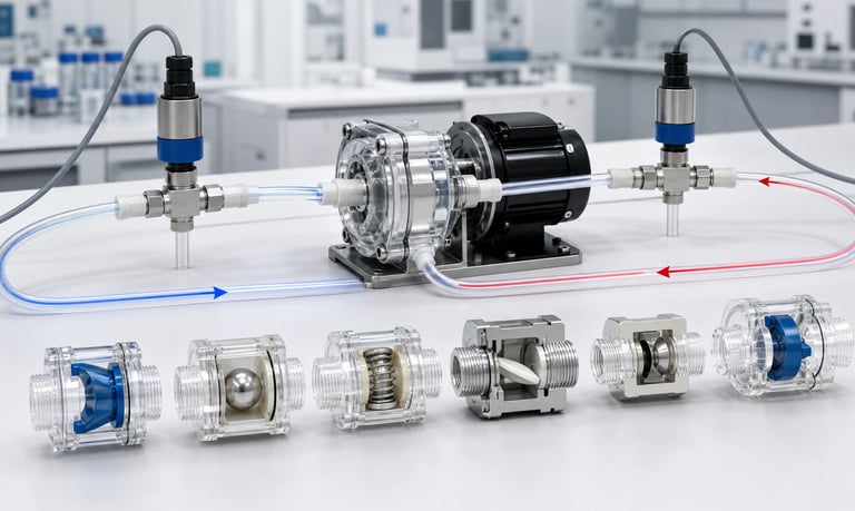
A check valve for a micro pump system must open reliably at available pump pressure, keep forward pressure loss within the flow budget, reseal with acceptable reverse leakage, respond to pulsating flow, tolerate the fluid and particles, and remain stable through temperature, cleaning, aging, orientation, and production variation.
How to Select a Check Valve for a Micro Pump System
A check valve allows flow in one direction and restricts reverse flow. In a micro pump system, it may help maintain prime, reduce backflow, isolate a branch, protect a sensor, or control fluid after the pump stops.
The valve also adds resistance, dead volume, moving parts, wetted materials, and another possible failure point. A cracking-pressure value alone does not show whether the valve will open at low flow, reseal after pulsating operation, pass viscous liquid, tolerate particles, or prevent the type of unintended flow the application actually has.
Selection should be based on measured forward and reverse behavior in the complete pump circuit, including fluid, pressure, speed, temperature, orientation, cleaning, aging, and production variation.
Define What the Valve Must Do
Start with the function rather than a preferred valve type.
Possible objectives include:
Prevent reverse flow after pump stop
Maintain a liquid-filled prime
Isolate parallel fluid branches
Protect a pump from reverse pressure
Stabilize diaphragm-pump direction
Limit cross-contamination
Prevent drain-back
Support pressure holding
Provide a defined opening threshold
Write the allowed forward pressure loss, reverse leakage, opening delay, closing response, internal volume, and service life under stated conditions.
Also define what the valve is not expected to do. A standard check valve may not provide positive shutoff, prevent forward siphoning, or isolate hazardous fluid after power loss.
Identify the consequence of a valve stuck open, stuck closed, partially restricted, leaking, or installed backward. The required fault controls depend on these outcomes.
Distinguish Check Valves from Shutoff and Anti-Siphon Valves
A check valve normally permits flow in its intended forward direction. If gravity drives fluid in that same direction, the valve may open and allow siphoning.
A normally closed shutoff valve is actively or passively closed until commanded open. It can provide a separate barrier but requires actuation, timing, power-state review, and fault validation.
An anti-siphon valve requires a defined upstream pressure before forward flow begins. Gravity pressure alone should remain below its opening threshold, while the pump must exceed it.
These functions are not interchangeable.
Ask:
Which direction is unintended flow?
Is the driving source reverse pressure or forward gravity head?
Must the barrier remain closed during power loss?
Is a small leakage rate acceptable?
Can the pump generate enough pressure to open the device?
Use the correct device or combination. Do not add a standard check valve and assume every post-stop flow problem is solved.
Understand Cracking Pressure
Cracking pressure is the differential pressure at which the valve begins to open under a defined test method. It is not necessarily the pressure required for full flow.
The measured value depends on:
Flow direction and pressure ramp
Detection threshold
Fluid or gas
Temperature
Valve orientation
Seal wetting
Spring or elastomer condition
Manufacturing tolerance
Previous pressure cycles
A catalog nominal value may represent a typical result, not a guaranteed minimum or maximum.
For a low-pressure micro pump, even a small opening requirement can consume a meaningful part of available pressure. At startup, the pump may compress bubbles or flexible tubing before the valve opens, delaying delivery.
Request the distribution or tolerance and test multiple production-representative valves. Measure the actual pressure at first useful flow, not only the first detectable movement.
Evaluate Full Forward Pressure Loss
Once open, the valve creates pressure loss that changes with flow, fluid viscosity, temperature, internal passage, and opening position.
Ask for or measure a pressure-loss curve across the required flow range.
High forward loss can cause:
Lower pump flow
Higher motor current and heat
Incomplete peristaltic tube or diaphragm chamber refill
Increased pulsation
Slower priming
Longer dosing time
Greater pressure stored in flexible tubing
Do not add cracking pressure and one pressure-drop value without checking how the supplier defines them. Valve behavior can be nonlinear and hysteretic.
Measure inlet and outlet pressure near the valve with production tubing, fittings, fluid, and temperature. Include clean and aged conditions.
The valve bore may be much smaller than the connected tube and become the dominant restriction.
Define Reverse Leakage
No check valve should be assumed to have zero reverse leakage. Define an acceptable rate, pressure, fluid, temperature, and observation time.
Reverse leakage can appear as:
Loss of prime
Backflow into a reservoir
Pressure decay
Cross-contamination
Dose error
Drainage after shutdown
Air entry into a liquid line
Leakage depends on reverse pressure. A valve that seals under a high reverse differential may not seat reliably at very low pressure, while another valve may leak more as pressure rises.
Measure both low and maximum credible reverse conditions. Include the actual orientation and fluid.
For gas, specify whether leakage is actual, standardized, or mass flow. For liquid, control temperature, viscosity, wetting, and evaporation.
A short visual check may miss a small leakage rate that becomes important during a long idle.
Check Resealing Pressure and Hysteresis
The differential pressure at which a valve closes may differ from the pressure at which it opens. This difference is hysteresis.
After forward flow, the valve element may remain displaced, wet, deformed, or stuck to a surface. It can take time or reverse pressure to reseat.
Evaluate:
Opening pressure
Pressure at useful forward flow
Closing or resealing behavior
Reverse leakage immediately after stop
Leakage after long idle
Response after repeated cycles
Performance after low and high flow
In a pulsating pump system, the valve may open and close during every cycle or remain partially open between pulses. The resulting waveform can differ from steady-flow tests.
Record pressure and flow with sufficient time resolution. A slow gauge may show only average behavior and miss valve chatter or delayed closure.
Match the Valve to Pump Type
Peristaltic Pumps
Peristaltic pumps already create directional flow through moving tube occlusion and do not require internal check valves for basic operation. An external check valve may support prime or backflow control but adds pressure and can worsen pulsation.
Check whether tube occlusion and rotor parking already provide enough reverse isolation. If an independent barrier is needed, define why.
Diaphragm Liquid Pumps
Diaphragm pumps normally include inlet and outlet valves inside the pump. An additional external valve may add protection or branch isolation but also increases opening pressure and chamber load.
Diaphragm Gas Pumps
Gas valves must respond to compressible flow and can be sensitive to humidity, particles, condensation, and leakage. Confirm pressure reference and flow basis.
Do not assume a valve suitable for one pump architecture or medium will behave the same in another.
Choose the Valve Mechanism
Common miniature check-valve mechanisms include spring-loaded poppets, balls, diaphragms, duckbill elements, umbrella elements, flappers, and other elastomeric or molded designs.
Each mechanism has tradeoffs involving:
Opening pressure
Flow capacity
Reverse leakage
Response speed
Orientation sensitivity
Particle tolerance
Dead volume
Material options
Noise
Cleaning
Production tolerance
Spring-loaded valves can provide a defined closing force but add metal or polymer components and may have higher opening pressure. Elastomeric valves can be compact and low mass but are sensitive to material stiffness, swelling, compression set, and temperature.
Ball valves may be affected by orientation, seat geometry, particles, and low differential pressure.
Choose from dynamic data for the actual application rather than a general mechanism ranking.
Evaluate Valve Response to Pulsation
Positive-displacement pumps deliver cyclic flow. The valve element must respond to changing pressure and may interact with fluid compliance.
Possible behaviors include:
Chatter
Delayed opening
Incomplete closure
Pressure spikes
Flow interruption
Acoustic clicking
Resonance with tubing or a chamber
Different average pressure loss from steady flow
Response depends on moving mass, spring or elastomer stiffness, damping, fluid viscosity, pulse frequency, pressure amplitude, and orientation.
Test at minimum and maximum pump speed. A valve that works at low frequency may remain partially open at high speed; a valve that works at high flow may not open consistently during small doses.
Measure instantaneous pressure or flow where the application is sensitive. Digital averaging can hide the physical interaction.
Account for Fluid Viscosity and Temperature
Viscosity increases pressure loss and can slow valve motion. A valve tested with water may not open, flow, or reseal the same way with oil, syrup, reagent, detergent, or cold fluid.
Temperature can change:
Fluid viscosity
Elastomer stiffness
Spring behavior
Seal dimensions
Surface wetting
Chemical interaction
Leakage
Test cold startup and hot steady operation. Include the full fluid range and any cleaning temperature.
For non-Newtonian fluids, valve gaps and flow acceleration create local shear. Apparent viscosity may differ from the reservoir measurement.
Do not compensate for high valve resistance only by increasing pump speed. This can worsen inlet refill, heat, pulsation, and tube or diaphragm wear.
Review Wetted Materials
Create a complete material list for the valve body, seal, spring, ball, diaphragm, adhesives, lubricants, and fittings.
Evaluate product, cleaner, rinse, vapor, and mixed waste at actual concentration, temperature, pressure, and time.
Material changes can cause:
Swelling
Hardening or softening
Tackiness
Corrosion
Stress cracking
Spring change
Valve-seat distortion
Permeation
Extractables or adsorption
A small stiffness or dimensional change can alter cracking pressure and leakage even when no visible damage appears.
Static compatibility data support screening but do not establish cyclic valve behavior. Test the finished valve dynamically after representative exposure and aging.
Do not infer food, medical, or regulatory suitability from a generic material name.
Evaluate Particles, Fibers, and Crystals
Particles can lodge on the valve seat, increase leakage, block opening, abrade surfaces, or alter pressure loss.
Define:
Particle-size distribution
Shape and hardness
Concentration
Settling and agglomeration
Fibers or flakes
Crystal growth during idle
Check the smallest valve passage and seat clearance, not only the connected tube bore.
A filter may protect the valve but adds pressure loss and can load over time. It may also remove desired solids from the product.
Test clean and realistically contaminated valves. Include restart after the longest idle period, when particles can settle on the seat.
If reverse leakage is critical, design detection or an additional barrier rather than assuming every particle will clear itself.
Consider Air Bubbles and Gas Pockets
Gas compresses before a valve opens. A bubble upstream of a spring-loaded valve can delay liquid delivery and store energy.
Bubbles can also:
Change apparent cracking behavior
Create pressure oscillation
Delay resealing
Cause intermittent doses
Expand after the valve
Collect in a valve chamber
Orient the valve to vent gas where possible. Avoid chambers or high points that trap bubbles.
Test dry prime, wet prime, partial prime, and bubble passage. A valve that seals well may make initial priming more difficult by increasing the pressure the pump must build against trapped gas.
Do not intentionally retain an uncontrolled gas pocket to soften pulsation. Its behavior changes with pressure, temperature, and orientation.
Check Installation Orientation
Gravity may affect balls, poppets, flappers, springs, and trapped gas. Supplier data may assume a particular orientation.
Test all approved product orientations, including:
Normal use
Tilt
Transport
Service position
Reservoir replacement
Vibration
Mark flow direction clearly. Incorrect installation can block flow or defeat reverse protection.
Use keyed ports, asymmetric fittings, controlled tube lengths, or assembly fixtures to prevent reversal.
Valve bodies and connected components should be supported so tubing does not carry excessive weight or bending load.
If the valve is mounted near a vibrating pump, verify leakage, noise, and retention after life and transport exposure.
Minimize Dead Volume and Retained Fluid
The valve body can trap product, cleaner, gas, or mixed waste. Internal cavities affect prime time, response, cross-contamination, and cleaning.
Review:
Internal volume
Flow path and crevices
Drainability
Orientation
Surface wetting
Product residence time
Cleaning access
Fluid released after stop
A larger valve may have lower pressure drop but more retained volume. A compact valve may create a narrow, difficult-to-clean passage.
For small doses, valve and line compliance can represent a significant fraction of the delivered amount.
Measure dose at the final outlet, including startup and shutdown. Do not calibrate only at the pump outlet while ignoring valve storage and nozzle dripping.
Plan Cleaning and Idle Management
Sticky fluid, crystals, dried residue, proteins, suspensions, and cleaners can change valve behavior after idle.
Define:
Flush fluid
Temperature and concentration
Flow and direction
Contact time
Drain and drying method
Maximum idle while filled
Number of cleaning cycles
Post-clean prime and verification
Reverse flushing may help some valves but may also force contamination into the pump or damage a valve not designed for reverse pressure.
Clear rinse at the outlet does not prove the seat is clean. Verify cracking pressure, flow loss, and reverse leakage after representative cleaning and idle cycles.
If the valve is not serviceable, define module replacement and disposal.
Locate the Valve Carefully
Placement affects prime, pressure, leakage, and the volume that remains uncontrolled.
An inlet check valve may help maintain prime but adds suction-side resistance and can cause incomplete pump filling.
An outlet check valve may reduce backflow but adds discharge pressure and stores volume upstream.
A valve near the process outlet can reduce uncontrolled downstream volume. A valve near the pump may protect more of the fluid path but leave a long line that drains or releases stored fluid.
Consider:
Pressure at the valve
Pump priming capability
Tube compliance
Service access
Cleaning and drainage
Temperature
Vibration
Sensor position
Test alternative locations if the objective is sensitive. Do not assume one standard placement suits every system.
Verify Startup and Shutdown Timing
The valve changes the pressure sequence when the pump starts and stops.
At startup, the pump must build enough differential pressure to open the valve. Short commands may end before stable flow begins.
At shutdown, the valve should reseal before unacceptable backflow occurs. Flexible tubing may continue delivering fluid as pressure relaxes.
Record:
Delay from motor command to valve opening
Delay to liquid at the outlet
Peak pressure
Valve closing time
Reverse flow
Post-stop dripping
First dose after idle
For systems with active shutoff valves, coordinate timing so a closed valve does not create excessive pressure or a late valve does not permit unwanted flow.
Test immediate power loss separately from normal software shutdown.
Control Production Variation
Valve performance varies with spring force, elastomer hardness, molded geometry, seat finish, assembly, lubricant, and material lot.
Ask the supplier:
Which characteristics are controlled?
Are cracking-pressure limits guaranteed or typical?
How is reverse leakage tested?
What fluid, temperature, orientation, and pressure are used?
Is every valve tested or only sampled?
What traceability and change notification are available?
Test multiple production lots across temperature and aging.
If the system depends on a narrow opening-pressure window, include worst combinations of pump pressure and valve tolerance.
An alternate valve with the same nominal cracking pressure is not automatically equivalent. Revalidate forward loss, response, leakage, materials, dead volume, and life.
Build a Representative Valve Test
Use the actual pump, fluid, tubing, fittings, pressure, speed, orientation, and control sequence.
Measure:
Cracking pressure by a defined method
Pressure at useful forward flow
Forward pressure-loss curve
Reverse leakage at low and maximum pressure
Opening and resealing time
Pulsating response
Prime time and bubble behavior
Dose and post-stop volume
Current, speed, and pump temperature
Performance after chemical, thermal, pressure, and life cycling
Include minimum and maximum fluid temperature, viscosity, pump voltage, flow, pressure, and multiple samples.
Test clean, aged, and realistically contaminated conditions. Preserve raw pressure and flow data rather than only pass or fail.
Use safe containment and stay within pump, valve, sensor, and fixture limits.
Check-Valve Selection Checklist
Valve function and failure consequences defined
Check, shutoff, and anti-siphon functions distinguished
Flow direction and pressure direction mapped
Cracking-pressure method, tolerance, and useful-flow threshold understood
Full forward pressure-loss curve measured
Reverse leakage limit, pressure, time, and fluid defined
Resealing pressure and hysteresis evaluated
Pump type and pulsation frequency included
Valve mechanism selected from application data
Fluid viscosity and temperature range tested
Exact wetted materials reviewed with product and cleaner
Particles, fibers, crystals, and contamination included
Bubbles, dry prime, and partial prime evaluated
Installation orientation and vibration tested
Dead volume, drainage, cleaning, and retained dose reviewed
Valve location optimized for prime and uncontrolled volume
Startup, normal stop, and immediate power loss tested
Production variation, supplier control, and alternate sources reviewed
Multiple samples tested after chemical, thermal, and life exposure
Common Check-Valve Mistakes
Selecting from nominal cracking pressure alone
Treating first opening as full-flow pressure
Ignoring forward pressure loss
Assuming zero reverse leakage
Testing high reverse pressure but not low-pressure resealing
Using a standard check valve to prevent forward siphoning
Ignoring pulsating valve response
Testing with water instead of viscous production fluid
Checking material compatibility but not valve stiffness
Ignoring particles on the seat
Installing without orientation control
Adding an inlet valve that prevents pump refill
Calibrating without startup delay and stored volume
Comparing alternate valves by size and pressure label only
Validating normal shutdown but not power loss
Frequently Asked Questions
What is cracking pressure in a check valve?
It is the differential pressure at which the valve begins to open under a defined test. More pressure may be required to obtain the application's useful flow.
Does a check valve stop siphoning?
Not necessarily. If siphoning drives liquid in the valve's permitted direction, a standard check valve may open. An anti-siphon or shutoff function may be required.
Why does a check valve reduce pump flow?
The valve adds opening pressure and forward resistance. Viscosity, flow, temperature, contamination, and valve position determine the actual pressure loss.
Can a check valve have reverse leakage?
Yes. Leakage depends on valve design, reverse pressure, fluid, temperature, particles, seat condition, orientation, and aging. Define and test an acceptable rate.
Where should a check valve be installed?
Placement depends on whether the objective is prime retention, pump protection, branch isolation, backflow control, or reducing uncontrolled outlet volume. Compare locations in the actual system.
How should a micro pump check valve be validated?
Measure opening, forward loss, reverse leakage, response, priming, dose, and post-stop behavior with the actual pump and fluid across temperature, pressure, speed, orientation, contamination, and aging.
Kamoer Check-Valve Integration Support
Kamoer can help evaluate pump pressure, fluid properties, valve location, cracking pressure, forward loss, reverse leakage, pulsation, materials, priming, and representative check-valve tests for OEM micro pump systems.
Related Stories
Kamoer Fluid Tech (Shanghai) Co., Ltd.
pump@kamoer.com