

How to Reduce Pulsation in a Small Pump System
TROUBLESHOOTING & FAQS
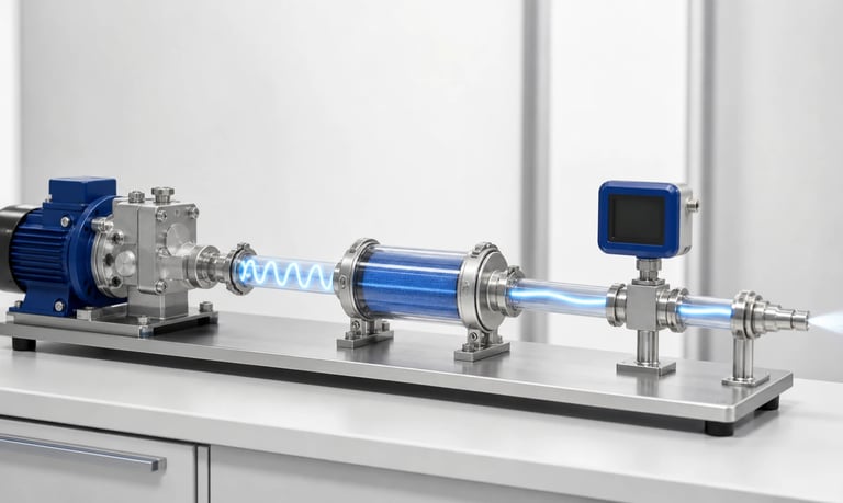

Reducing pulsation in a small pump system requires a measured system-level approach that matches the pump mechanism, speed, tubing, fluid-path resistance, damping, channel phasing, control response, and dispensing method to the application's allowable flow and pressure variation.
How to Reduce Pulsation in a Small Pump System
Small positive-displacement pumps move fluid in repeated mechanical cycles, so instantaneous flow and pressure are rarely perfectly steady. Peristaltic rollers, diaphragm strokes, piston motion, and check-valve opening can all create pulses even when the average flow is correct.
Reducing pulsation starts with defining what the application actually needs. A visible pulse in transparent tubing may be harmless, while a much smaller pressure ripple can disturb a spray nozzle, flow sensor, mixing ratio, optical measurement, or short timed dose. The most effective solution usually combines pump selection, operating point, fluid-path design, and measurement rather than relying on one added component.
Confirm That the Problem Is Pulsation
Pulsation is a repeatable variation linked to the pump cycle. Other faults can produce irregular flow that looks similar but requires a different correction.
Compare the flow or pressure signal with pump speed or rotor position. A stable repeating waveform at the pump frequency or one of its harmonics is likely mechanism-related pulsation. Random or slowly drifting behavior may instead indicate:
Air entering through an inlet connection
Incomplete priming or trapped bubbles
Inconsistent check-valve sealing
Tube wear or changing occlusion
Reservoir vent restriction
Particle or crystal interference
Fluid separation or viscosity change
Unstable motor speed or supply voltage
Sensor noise, aliasing, or unsuitable filtering
Correct leaks, bubbles, restrictions, worn consumables, and control instability before sizing a damper. A damper may hide the visible symptom without resolving the underlying fault.
Define an Acceptable Pulsation Level
"Smooth flow" is not a measurable requirement. Define the controlled variable, location, operating range, and calculation method.
Useful requirements may include:
Maximum peak-to-peak flow variation
Maximum pressure ripple at a sensor or nozzle
Allowed variation over a specified time window
Dose repeatability for a defined dispense volume
Maximum spray, coating, or mixing nonuniformity
Allowed sensor oscillation after signal processing
Settling time after start, stop, or speed change
State whether the limit applies to instantaneous flow, a moving average, one pump revolution, or a complete dose. Also define the sensor bandwidth and sampling rate. A percentage without a measurement method can produce inconsistent test results.
Evaluate the minimum and maximum flow, because a solution that works at one speed may not work across the full range.
Measure the Existing Waveform Correctly
Use a flow or pressure sensor with enough bandwidth to capture the relevant peaks. A slow sensor may display only the average. A fast sensor combined with a low sampling rate can create aliasing and show a misleading lower-frequency oscillation.
Record:
Instantaneous flow or pressure
Average flow
Pump command and actual speed
Rotor or stroke position where available
Fluid temperature and viscosity
Inlet vacuum and outlet pressure
Tubing, fittings, valves, and nozzle configuration
Sensor model, position, range, bandwidth, and sample rate
Measure at the point that matters to the process. A waveform near the pump outlet may be different from the waveform at the end of a long compliant tube.
Do not let the measurement setup dominate the result. A sensor with a narrow passage, large internal volume, or flexible membrane can add resistance or damping that will not exist in production.
Choose a Pump Mechanism Suited to the Requirement
Every pump architecture has a characteristic delivery pattern. The correct starting point depends on required average flow, pressure, dose size, fluid compatibility, maintenance, and acceptable ripple.
Peristaltic pump pulsation is influenced by roller entry and exit, roller spacing, occlusion, tube recovery, and the number of compression events. Diaphragm pump pulsation depends on stroke profile, chamber volume, valve timing, valve response, and drive method. Piston and gear pumps have their own displacement and leakage patterns.
More rollers, chambers, pumping elements, or phases may create smaller and more frequent delivery events, but the result depends on geometry and phasing. A higher event frequency can also shift vibration into a range that affects sensors or structures.
Compare candidate pumps using measured output in the intended system. Do not assume that one feature, such as roller count, guarantees lower pulsation.
Operate the Pump in a Better Speed Range
Pump speed changes pulse frequency and may change amplitude. At very low speed, individual displacement events are separated in time and can be obvious. At high speed, a peristaltic tube or pump chamber may not refill completely, particularly with viscous liquids or inlet restriction.
One practical approach is to use a larger displacement per revolution at a lower speed, or a smaller displacement at a higher pulse frequency that is easier to damp. Which approach works better depends on the pump waveform and downstream system.
Build a speed-to-pulsation map rather than testing one nominal point. Track average flow as well, because a setting that looks smoother must still deliver the required output.
Avoid running close to a motor's unstable minimum speed or the pump's incomplete-refill region. Confirm performance at supply-voltage and temperature extremes.
Reduce Unnecessary Fluid-Path Resistance
Narrow tubing, small fittings, filters, check valves, flow sensors, mixers, and nozzles convert cyclic flow into pressure peaks. Higher viscosity and longer lines increase this effect.
Review the entire path for:
Fittings with bores smaller than the tubing
Abrupt contractions or expansions
Sharp bends and kinked flexible tube
Long lengths of small-bore tubing
Filters near the end of service life
Valves with high opening pressure
Nozzles sized only for average flow
Manifolds or sensor ports with trapped air
Reducing one dominant restriction may lower pressure ripple more effectively than adding compliance. Measure both average pressure loss and instantaneous pressure at realistic clean and loaded conditions.
The inlet also matters. Restricted refill can change the volume delivered on each stroke and create irregular pulses. Keep the inlet short, adequately sized, airtight, and properly vented at the reservoir.
Use Tubing Compliance Deliberately
Flexible outlet tubing expands slightly during a pressure peak and releases stored fluid as pressure falls. This distributed compliance can smooth the output without a separate damper.
Compliance depends on tubing material, inner diameter, wall thickness, length, temperature, reinforcement, aging, and pressure. Too much compliance can create slow response, stored volume, delayed shutoff, or an unwanted dose after the motor stops.
Tubing also interacts with fluid inertia and system resistance. Certain combinations can amplify oscillation or create resonance rather than suppress it.
If tubing compliance is part of the design, control the production tube specification and routing. Test aged tubing, chemical exposure, temperature extremes, and lot variation. Do not treat an accidental loop of soft tubing as a repeatable damping component.
Add a Pulsation Damper When Appropriate
A pulsation damper uses a compliant volume to absorb part of the incoming pulse and release fluid between pump events. Designs may use an elastic membrane, flexible chamber, gas volume, or another compliant element.
Damper performance depends on:
Internal volume and compliance
Fluid pressure and pulse frequency
Membrane or chamber material
Gas charge or preload, where applicable
Flow resistance into and out of the damper
Orientation and trapped-air behavior
Distance from the pump and protected component
A damper is not automatically better when larger. Excess volume can slow priming, lengthen settling time, retain product, complicate cleaning, and continue dispensing after pump stop.
Place the damper based on the objective. Locating it near the pump may reduce transmission through the whole outlet line. Locating it near a sensitive nozzle or sensor may better control the local waveform. Test both if routing allows.
Confirm pressure capability, fatigue life, leakage containment, wetted-material compatibility, drainage, sanitizing, and replacement requirements. For liquids that release gas or trap bubbles, distinguish intentional compliance from uncontrolled gas pockets.
Combine Multiple Pumping Channels Out of Phase
Two or more pump channels can be phased so one channel delivers while another passes through a low-flow part of its cycle. Properly combined outputs can reduce the net ripple.
Successful phasing requires:
Predictable displacement from each channel
Controlled relative phase
Similar outlet resistance
Balanced calibration
A manifold with suitable internal geometry
Stable behavior as consumables age
Simply connecting two pumps does not guarantee cancellation. If they run in phase, the pulses may add. If their flow or pressure responses differ, cancellation may work only at one operating point.
Multi-channel systems add motors, drivers, sensors, tubing, and control complexity. Evaluate whether the reduction justifies the added size, cost, failure modes, and calibration work.
Optimize Dosing Timing and Rotor Position
For discrete doses, the objective may be repeatable volume rather than perfectly smooth instantaneous flow. Timing a dose to include complete and repeatable pumping cycles can be more effective than damping every pulse.
Very short commands may capture different fractions of a roller or diaphragm cycle. Start and stop delays, motor acceleration, elastic line expansion, and nozzle pressure can then dominate the result.
Possible strategies include:
Dispensing an integer number of complete pump cycles
Starting from a known rotor or stroke position
Using a stepper motor or position feedback
Applying a repeatable acceleration and deceleration profile
Using a slower finishing stage near the target dose
Measuring delivered mass or volume with feedback
Rotor-position control cannot correct inlet bubbles, tube wear, valve leakage, or changing viscosity. Validate the complete sequence after idle and across pressure conditions.
Apply Feedback Without Chasing Every Pulse
A flow or pressure control loop can regulate average output or compensate for slower disturbances. It may not be practical to cancel each mechanical pulse if the sensor, motor, driver, and fluid path lack sufficient bandwidth.
If controller gain is too aggressive, the motor can accelerate and decelerate in response to the natural pulse waveform, making pressure ripple, noise, and wear worse. Select the measurement filter and control bandwidth with knowledge of the pump frequency.
Separate objectives where possible:
Mechanical and fluidic measures reduce high-frequency cyclic ripple.
Feedback corrects average flow, pressure changes, viscosity drift, or reservoir-level effects.
Signal processing provides a stable displayed value without claiming that physical pulsation is gone.
A filtered sensor display may look smooth while the nozzle still receives pulsating flow. Verify the process output independently.
Manage Bubbles and Compressible Volume
Gas bubbles add compliance, but uncontrolled bubbles are poor pulsation dampers. Their volume changes with pressure, temperature, orientation, and time. They may migrate through the system, disturb sensing, delay dosing, or release stored liquid after shutdown.
Prevent inlet air leaks, maintain adequate reservoir level, vent the source correctly, and use a validated priming sequence. Avoid high points or chambers that trap gas unless they are intentionally designed and controlled.
If the fluid naturally outgasses, evaluate pressure, temperature, residence time, and wetted-surface effects. Degassing or a bubble separator may be necessary before optimizing the remaining mechanical ripple.
Prevent Resonance, Noise, and Structural Coupling
The pump pulse can excite flexible tubing, panels, brackets, valves, or sensor mounts. Audible noise and vibration may therefore be much larger than the fluid ripple alone suggests.
Change one factor at a time while monitoring both the fluid signal and structural response. Useful adjustments may include:
Shorter unsupported tubing spans
Secure but non-crushing clamps
More rigid pump and sensor mounting
Isolation between the pump and enclosure
A different tube length or routing
Moving the operating speed away from a resonant frequency
Soft mounting can reduce transmitted vibration but should not allow pump motion to strain fittings or alter occlusion. Confirm performance in the final enclosure, not only on an open bench.
Check the Side Effects of Each Solution
Every pulsation-reduction method introduces tradeoffs. Review them before freezing the design:
A different pump head or mechanism changes pulse generation at the source but may change size, cost, pressure, flow range, and consumable life.
A speed change shifts pulse frequency and refill behavior but also affects average flow, dose resolution, motor range, and noise.
Larger fluid passages reduce pressure ripple from resistance but add internal volume and may slow priming.
Compliant tubing provides distributed damping but can delay response, store fluid, age, and vary between lots.
A pulsation damper can substantially smooth local pressure or flow but adds retained fluid, cleaning work, settling time, and maintenance.
Phased pump channels can cancel part of the cyclic output but require additional controls, calibration, manifolding, and components.
Feedback control can correct average or low-frequency variation but introduces sensor delay, tuning requirements, and possible instability.
Signal filtering stabilizes displayed measurements but does not reduce physical pulsation.
Confirm that the chosen solution still meets priming, shutoff, cleaning, material, pressure, service-life, and fault requirements.
Validate the Final System
Test the actual pump, fluid, tubing, fittings, valves, sensors, damper, nozzle, software, and enclosure. Include production tolerances rather than only one optimized prototype.
At minimum, evaluate:
Minimum, typical, and maximum flow
Minimum and maximum pressure
Full viscosity and temperature range
New and aged tubing, valves, or membranes
Clean and realistically loaded filters
Minimum and maximum supply voltage
Startup, steady operation, speed changes, and shutdown
First dose after the longest idle period
Dry and partially primed conditions
Empty source, inlet leak, blockage, and sensor faults
Record the unfiltered waveform where possible, even if the acceptance metric uses a filtered value. This preserves evidence of peak pressure and transient behavior.
Pulsation Troubleshooting Checklist
Define the allowed flow or pressure variation and measurement bandwidth
Confirm the waveform is synchronized with the pump cycle
Rule out leaks, bubbles, worn tubing, valve faults, and unstable speed
Measure at the process-critical location
Map pulsation across the full pump speed range
Record inlet vacuum, outlet pressure, viscosity, and temperature
Remove avoidable restrictions and verify reservoir venting
Compare pump mechanisms, heads, roller counts, or chamber phasing
Evaluate controlled tubing compliance
Size and locate any damper using test data
Check dose timing and complete-cycle control
Tune feedback below the frequency it can reliably control
Test structural vibration and acoustic resonance in the enclosure
Review priming, shutoff delay, cleaning, and retained volume
Validate multiple pumps and consumable lots after aging
Common Pulsation-Reduction Mistakes
Adding a damper before checking for inlet air leaks
Measuring only average flow
Using a sensor too slow to capture the waveform
Comparing results from different sensor locations
Assuming more rollers always produce a smoother output
Increasing speed without checking inlet refill
Adding soft tubing without controlling its dimensions and aging
Filtering the display and declaring the physical pulse solved
Tuning feedback to chase each mechanical event
Ignoring the extra dose released from stored pressure after stop
Testing with water when production fluid is more viscous
Optimizing an open bench instead of the final enclosure
Frequently Asked Questions
What is the fastest way to reduce pump pulsation?
First remove avoidable restrictions, air leaks, and trapped bubbles, then test speed and fluid-path changes. A damper can help, but it should be sized and located from measured waveform data.
Does a pulsation damper improve dosing accuracy?
It can smooth instantaneous output, but it may also store fluid and delay delivery after start or stop. Dose accuracy still depends on calibration, timing, pressure, bubbles, and pump condition.
Do more rollers always reduce peristaltic pump pulsation?
No. More rollers change pulse frequency and spacing, but track geometry, occlusion, tubing, speed, pressure, and refill behavior determine the final waveform.
Can software filtering eliminate pump pulsation?
Filtering can stabilize a displayed sensor value, but it does not remove the physical flow or pressure variation reaching the process.
Why does pulsation become worse with viscous liquid?
Higher viscosity increases inlet and outlet resistance, can prevent complete refill, and can create larger pressure changes through narrow passages.
Where should a pulsation damper be installed?
Placement depends on the objective. Near-pump placement may protect the outlet path, while placement near a sensitive nozzle or sensor may better control local ripple. Compare both in the real system.
Kamoer Pulsation-Reduction Support
Kamoer can help evaluate pump mechanism, head geometry, speed, tubing, pressure, fluid-path resistance, damping, channel phasing, dose timing, sensing, control, and representative OEM pulsation testing.
Related Stories
Kamoer Fluid Tech (Shanghai) Co., Ltd.
pump@kamoer.com