

How to Reduce Noise and Vibration in an OEM Pump System
MICRO PUMP BASICS
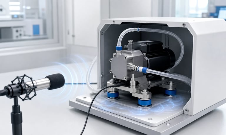
Noise in an OEM pump system can travel through air, mounting structures, tubing, fluid pressure pulses, and connected components; effective reduction starts with source identification and combines suitable pump operation, isolation, routing, structural control, and production validation.
How to Reduce Noise and Vibration in an OEM Pump System
A compact pump can be quiet on a test bench yet become objectionable inside an OEM product. The enclosure, mounting bracket, tubing, valves, panels, reservoir, and control method can amplify forces that were barely noticeable at the component level.
Noise reduction works best when the transmission path is identified before parts are added. Airborne motor or valve sound, structure-borne vibration, and fluid-borne pressure pulsation require different solutions. Soft mounts alone cannot correct a cavitating inlet, and software filtering cannot remove a vibrating panel.
The goal is not necessarily the lowest possible sound level. The design should meet a measurable product requirement across the complete operating range, production variation, component aging, and foreseeable fault conditions.
Define the Noise and Vibration Requirement
Words such as "quiet" and "low vibration" are subjective. Define the operating state, measurement position, environment, and acceptance method.
Requirements may include:
Sound-pressure level at a specified distance and orientation
Frequency-weighted or unweighted acoustic result
Maximum tonal component or narrow-band peak
Vibration acceleration or velocity at a defined mounting point
Movement limit for a sensor, nozzle, camera, or optical assembly
User-perceived sound during a complete operating sequence
Maximum sound during priming, normal pumping, and shutdown
Transient limits for valve switching or speed changes
Specify background noise, room conditions, product orientation, supporting surface, fluid, pressure, pump speed, and enclosure state. An open product measured in a noisy laboratory cannot be compared directly with a closed product in a quiet room.
Where perception matters, objective measurements and controlled listening evaluations can complement each other. Do not replace traceable engineering data with informal comments from different environments.
Separate the Main Transmission Paths
Pump-system noise usually reaches the user through one or more paths.
Airborne Noise
Airborne sound can come directly from the motor, gears, rollers, valves, fans, and moving pump components. Openings, vents, seams, and thin panels influence how it escapes the product.
Structure-Borne Vibration
Reaction forces pass through pump feet, fasteners, brackets, tubing, and cables into the chassis. Large panels can radiate more sound than the pump itself.
Fluid-Borne Pulsation
Cyclic flow creates pressure waves that travel through liquid or gas lines. Valves, sensors, filters, nozzles, reservoirs, and flexible tubing may vibrate or produce sound in response.
Flow-Induced Noise
High velocity, sharp restrictions, cavitation, bubbles, turbulent jets, and leaking valves can create broadband or intermittent noise.
Use isolation tests to identify the dominant path. Temporarily supporting a tube, changing a bracket constraint, operating into a low-resistance reference path, or measuring panels with an accelerometer can reveal where energy travels. Temporary changes are diagnostic tools, not automatically production solutions.
Establish a Repeatable Baseline
Measure the original system before modifying it. Record the configuration in enough detail to reproduce the result.
Include:
Pump, motor, gearbox, head, and component revision
Pump speed, flow, inlet vacuum, and outlet pressure
Fluid identity, viscosity, temperature, and bubble condition
Mount material, fasteners, torque, and isolation parts
Tubing material, dimensions, length, routing, and clamps
Valve, filter, sensor, damper, reservoir, and nozzle configuration
Driver, PWM, current limit, and firmware settings
Enclosure panels, covers, seals, vents, and support surface
Microphone and vibration-sensor location and mounting
Run the system long enough to capture startup, priming, thermal stabilization, normal operation, speed changes, and shutdown. A single steady-state reading may miss the most noticeable event.
Retain time recordings and frequency spectra where possible. Overall level alone can hide a strong tone that dominates user perception.
Identify the Dominant Frequencies
Mechanical and fluid events create characteristic frequencies related to motor rotation, gear engagement, peristaltic roller passage, diaphragm strokes, valve motion, PWM, and structural resonance.
Compare frequency peaks with:
Motor rotational speed
Gear ratio and gear-mesh events
Number of rollers or pump strokes
Multiple pumping channels and their phase
Valve actuation rate
Electrical switching frequency
Fan or other product components
A peak that moves when pump speed changes is often connected to the source or its harmonics. A panel resonance may respond strongly only when that moving frequency passes through a narrow range.
Frequency analysis does not by itself identify the physical path. Combine it with accelerometer measurements, microphone position changes, operating-point changes, and controlled mechanical isolation.
Select a Pump for the Acoustic Requirement
Noise performance begins with pump architecture and operating point. A pump forced to run near a mechanical, fluidic, or control limit will be harder to quiet.
Compare candidate pumps at the required flow and pressure rather than at unloaded free flow. Consider:
Motor type and commutation
Gearbox design and reduction ratio
Peristaltic roller count and track geometry
Diaphragm stroke, valve design, and number of chambers
Bearing and linkage arrangement
Required speed and torque margin
Pulsation and pressure ripple
Size, mass, mounting, and heat
A larger-displacement pump may deliver the required flow at lower speed, but lower-frequency events may excite the enclosure. A smaller pump at higher speed may move the dominant tone upward while increasing motor or gear noise. Test both source level and integrated-product response.
Do not select from a single published sound value unless its operating conditions and test method match the application closely enough to be useful.
Choose a Quieter Operating Speed
Noise and vibration rarely change linearly with speed. Certain speeds align pump forcing with a bracket, panel, tubing, or reservoir resonance.
Create a speed sweep under representative fluid and pressure conditions. Record flow, pressure, current, temperature, sound, and vibration. Identify narrow ranges with strong tones or structural response.
Possible strategies include:
Operating away from resonant speed bands
Using a different tube or pump displacement to achieve the same flow elsewhere
Accelerating quickly but safely through a noisy transition range
Using a validated prime speed and a quieter steady speed
Avoiding unstable very-low-speed motor operation
Changing speed also affects tube refill, valve response, pulsation, dose resolution, motor heating, and service life. Verify the entire performance requirement after acoustic optimization.
Design the Pump Mount as a System
The mount controls how forces enter the chassis. A very rigid mount can transmit vibration efficiently, while an excessively soft mount can allow large pump motion and create tube, wire, or impact problems.
An isolation mount should consider:
Pump mass and center of gravity
Excitation frequency range
Isolator stiffness and damping
Static deflection and available clearance
Compression, shear, and installation direction
Fastener preload and hard contact paths
Temperature, chemical exposure, aging, and compression set
Shock, transport, and product orientation
Avoid bypassing the isolator with an overtightened bolt, rigid spacer, cable tie, tube, or connector. These parallel paths can transmit more vibration than the mount.
Soft mounting must not let the pump strike the enclosure, pull fittings loose, alter peristaltic occlusion, or fatigue wiring. Check motion during startup, blockage, transport, and the lowest excitation frequency.
Use controlled assembly instructions for fasteners and isolators. Variation in torque, washer stack, or rubber compression can cause unit-to-unit acoustic differences.
Improve Brackets and Structural Panels
A bracket should support the pump without acting like a flexible sounding board. Thin, broad, lightly damped panels can convert small forces into audible radiation.
Potential changes include:
Shortening unsupported bracket spans
Adding bends, ribs, beads, or local thickness
Moving attachment points
Increasing joint stiffness
Adding constrained damping in a validated location
Reducing panel area excited by the pump
Relocating the pump away from sensitive surfaces
Changing mass or stiffness to move a resonance
Simply adding mass may lower vibration at one frequency while creating another issue. Foam placed against a panel may damp motion, but it can also retain heat, absorb liquid, age, or create assembly variation.
Use modal or operational measurements when the structure is complex. Confirm changes in the closed product with production-representative materials and fasteners.
Decouple Tubing and Cables
Tubing can act as both a vibration isolator and a transmission bridge. Short, taut, stiff tubing may carry pump motion directly to a reservoir, valve, sensor, or enclosure wall.
Review:
Tube material and stiffness
Length between pump and first support
Bend radius and routing direction
Tension, twist, and side load at pump ports
Contact with panels or sharp edges
Clamp material, spacing, and compression
Temperature and chemical aging
Pressure-driven expansion and movement
A controlled flexible loop may reduce structure-borne transmission, but excessive length adds internal volume, pressure loss, compliance, prime time, and retained fluid.
Clamps should prevent impact and rubbing without crushing the tube or creating a hard vibration path. Define routing and clamp positions on production drawings.
Wires and connectors can also bypass soft mounts. Provide enough controlled flexibility while preventing abrasion and intermittent electrical contact.
Reduce Fluid Pulsation and Pressure Ripple
Fluid-borne pulses can excite tubing, valves, filters, sensors, and nozzles. Measure pressure or instantaneous flow along with vibration to determine whether the signals are related.
Reduction methods may include:
A pump head or mechanism with a smoother delivery pattern
A different speed range
Reduced unnecessary fluid-path restriction
Larger-bore fittings and gentler transitions
Controlled compliant tubing
A properly sized pulsation damper
Multiple pump channels operated out of phase
Optimized valve and nozzle selection
A damper can lower pressure ripple but adds stored volume, response delay, cleaning work, and possible post-stop delivery. Size and position it using measured system behavior.
Do not confuse a smooth sensor display with smooth physical flow. Digital filtering changes the reported signal, not the pressure waves reaching the hardware.
Prevent Cavitation, Air Entry, and Valve Chatter
Inlet restriction, high viscosity, excessive suction lift, low reservoir level, or high speed can prevent complete filling. Vapor formation, outgassing, and inlet leaks introduce bubbles that create irregular noise.
Check:
Reservoir venting and pickup submergence
Inlet tubing diameter and length
Filters and valves for restriction
Inlet vacuum at worst conditions
Fluid temperature and viscosity
Air leaks at fittings
Priming procedure and bubble traps
Diaphragm-pump valves may chatter or close sharply under certain pressure, speed, or gas conditions. Contamination, stiffness change, and wear can make the sound intermittent.
Correct the fluid condition before adding acoustic insulation. Cavitation or incomplete refill can also reduce flow and damage components.
Optimize Motor and Driver Settings
The driver influences motor torque ripple, speed stability, switching noise, and structural excitation. Use settings approved for the motor and pump assembly.
Review:
PWM or commutation frequency
Current limit and current ripple
Acceleration and deceleration profiles
Closed-loop speed-control tuning
Stepper microstepping and resonance behavior
Holding current and idle strategy
Supply-voltage stability
Cable routing and electrical connections
Moving an electrical switching frequency can reduce an audible tone, but it may affect driver losses, motor heat, electromagnetic compatibility, torque, and control resolution.
Aggressive speed control can react to natural roller or diaphragm load variation and create additional modulation. Record command, actual speed, current, pressure, and vibration together before changing control gains.
Verify settings at minimum and maximum voltage, temperature, load, and production motor variation.
Treat the Enclosure Carefully
An enclosure can block airborne sound, but it can also amplify structure-borne vibration and trap heat.
Effective enclosure work may involve:
Sealing unnecessary acoustic openings
Designing a longer or baffled ventilation path
Adding absorption where it remains clean and dry
Damping resonant panels
Preventing pump or tubing contact with covers
Separating the pump chamber from sensitive user areas
Managing airflow without a new tonal fan source
Sound absorption, vibration damping, and vibration isolation are different functions. A soft porous absorber may reduce reflected airborne sound but do little for a panel driven through a rigid bracket.
Materials must suit temperature, fire, chemical, moisture, contamination, and service requirements. Adhesives and foams can age or detach.
Repeat thermal tests after closing openings or adding insulation. A quieter enclosure that overheats the motor, driver, fluid, or tubing is not a complete solution.
Control Valves, Fittings, and Moving Lines
Solenoid valves, check valves, pinch valves, regulators, and nozzles can create clicks, chatter, pressure spikes, or turbulent noise.
Evaluate:
Valve opening and closing pressure
Actuation speed and drive profile
Pressure before switching
Mounting and contact with the chassis
Internal flow passage and restriction
Fluid viscosity, particles, and bubbles
Wear, contamination, and temperature
A softer valve drive or changed timing may reduce impact, but it must preserve sealing and response. A restricted valve can also increase pump load and fluid pulsation.
Support moving tubing so it does not strike panels during each pulse. Observe the system with the enclosure open only for diagnosis, then confirm it closed because cover constraints can change movement.
Manage Startup, Priming, and Shutdown Sounds
The loudest event may occur for only a few seconds. Priming can involve air-liquid mixtures, high speed, changing load, and valve chatter. Shutdown can release pressure or move a valve abruptly.
Develop a controlled sequence that may include:
A validated prime speed that avoids incomplete inlet refill
Confirmation that fluid has reached the intended point
A smooth transition to operating speed
Pressure release or reverse motion where appropriate
Coordinated pump and shutoff-valve timing
A maximum prime time and fault response
Do not slow priming only for sound if the pump then fails to move viscous or cold fluid. Do not accelerate it without checking suction, bubbles, and current.
Evaluate the first operation after long idle, dry start, low reservoir, air ingestion, blockage, and immediate power loss. The sound profile can be a useful fault indicator, but it should not be the only protection.
Validate Across Production and Life
Acoustic performance varies with pump units, motors, gears, tubing lots, valves, isolators, fastener torque, and enclosure assembly.
Test multiple representative units and include:
Minimum, typical, and maximum pump speed
Minimum and maximum pressure
Fluid viscosity and temperature range
Full and low reservoir level
New and aged tubing, valves, and pump components
Minimum and maximum supply voltage
Cold startup and thermal steady state
Product orientations and support surfaces
Cleaning, maintenance, and component replacement
Environmental and transport exposure as required
Track noise and vibration during life testing. Wear can create new gear tones, valve leakage, tube impact, bearing noise, or mounting looseness before average flow leaves its allowed range.
End-of-line screening may use current, speed, pressure, vibration, or an acoustic metric to detect assembly faults. Correlate the production test with the full engineering measurement and control background noise carefully.
Noise and Vibration Checklist
Acoustic and vibration limits defined with conditions and measurement method
Airborne, structure-borne, and fluid-borne paths separated
Repeatable baseline recorded in the final enclosure
Frequency peaks compared with motor, gear, roller, stroke, valve, and PWM events
Candidate pumps compared at required flow and pressure
Speed sweep completed under representative load
Pump mount stiffness, damping, travel, and hard bypass paths reviewed
Brackets and panels checked for resonance
Tubing and cables routed without tension or enclosure contact
Inlet vacuum, outlet pressure, pulsation, and bubbles measured
Cavitation, incomplete refill, and valve chatter ruled out
Motor-driver settings verified for heat, torque, and control stability
Enclosure treatments reviewed for ventilation, aging, and contamination
Startup, priming, valve switching, and shutdown tested
Multiple production-representative units evaluated
Noise and vibration tracked through life and environmental exposure
End-of-line test correlated with engineering results
Common Noise-Reduction Mistakes
Evaluating the pump only in free air
Adding soft mounts without checking tube and cable bypass paths
Using an isolator so soft that the pump strikes the enclosure
Treating acoustic foam as a solution for structure-borne vibration
Optimizing one speed while ignoring the full operating range
Ignoring fluid pulsation, bubbles, or cavitation
Filtering a sensor display instead of reducing the physical disturbance
Adding enclosure material without repeating thermal tests
Comparing sound readings from different rooms or microphone positions
Measuring only a single overall level and missing a dominant tone
Testing one prototype but not production variation
Ignoring startup, priming, and shutdown events
Changing mounting, speed, and tubing simultaneously without isolating the cause
Assuming quieter operation automatically preserves flow, pressure, and life
Frequently Asked Questions
Why is a micro pump louder inside the enclosure?
Mounts, tubing, brackets, and panels can transmit and amplify vibration, while the enclosed air space can reinforce sound. The enclosure may also increase temperature and change pump behavior.
Do rubber mounts always reduce pump noise?
No. Isolation depends on pump mass, excitation frequency, mount stiffness, damping, preload, and bypass paths. An unsuitable mount can increase motion or amplify part of the frequency range.
Can changing pump speed reduce noise?
Yes. Moving away from a structural or fluid resonance can reduce a strong tone, but the new speed must still meet flow, pressure, priming, thermal, and service-life requirements.
Does a pulsation damper make a pump quieter?
It may reduce fluid-borne pressure ripple and vibration in connected components. It also adds volume, response delay, cleaning needs, and possible post-stop delivery.
Why does pump noise increase after long operation?
Temperature, tubing behavior, valve condition, motor or driver heat, lubrication, pressure, and component wear can change during operation. Measure flow, pressure, current, and temperature with the sound.
How should pump noise be checked in production?
Use a controlled end-of-line method correlated with engineering tests. Define the operating point, fixture, background noise, sensor position, limits, and handling of abnormal units.
Kamoer OEM Noise and Vibration Support
Kamoer can help evaluate pump architecture, operating speed, mounting, tubing, fluid pulsation, driver settings, enclosure integration, component variation, and representative noise and vibration testing for OEM pump systems.
Related Stories
Kamoer Fluid Tech (Shanghai) Co., Ltd.
pump@kamoer.com