

How to Protect a Micro Pump System from Blockage and Overpressure
TROUBLESHOOTING & FAQS
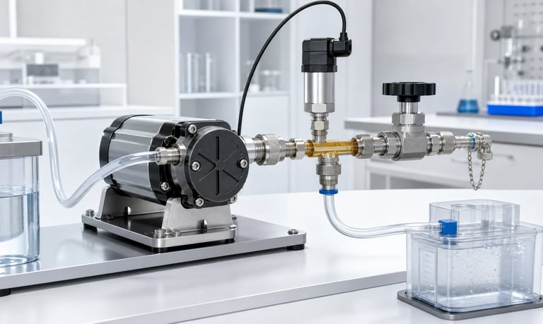
Micro pump overpressure protection requires a defined pressure envelope, components rated for steady and transient loads, detection of blocked or restricted flow, a safe pump and valve response, and where necessary an independent relief or bypass path that remains effective through fluid variation, contamination, temperature, aging, and power loss.
How to Protect a Micro Pump System from Blockage and Overpressure
A blocked outlet can cause a positive-displacement micro pump to build pressure rapidly. Tubing, fittings, filters, sensors, valves, pump chambers, and reservoirs may see loads above their normal operating condition before software reacts.
Overpressure can also occur without a completely blocked line. A loaded filter, closed valve, kinked tube, narrow nozzle, crystal deposit, thermal expansion, or incorrect shutdown sequence can create sustained or transient pressure.
Protection should not rely on one nominal pump-pressure value. The OEM must define the pressure envelope, component limits, detection method, pump and valve response, independent protection where needed, and recovery after the fault.
Define the Pressure Envelope
Map pressure for every operating and nonoperating state.
Include:
Normal minimum and maximum flow
Startup and priming
Valve opening and closing
Pump acceleration and deceleration
Clean and loaded filters
Minimum and maximum fluid viscosity
Cold and hot conditions
Reverse flow or suck-back
Outlet blockage
Inlet blockage
Thermal expansion while stopped
Siphoning and static head
Cleaning and service
Measure pressure at the pump outlet and at vulnerable components. Pressure can differ along the path because of line loss and trapped volume.
Define normal operating, warning, shutdown, relief, proof, and structural limits separately. Keep appropriate margin for sensor error, production tolerance, transients, and aging.
Do not use a component's burst value as a normal control threshold.
Identify Foreseeable Blockage Sources
Blockage can develop suddenly or gradually.
Possible sources include:
Closed or incorrectly timed valve
Kinked or crushed tubing
Loaded filter
Small nozzle or needle
Crystals or dried product
Particles, fibers, or agglomerates
Frozen or highly viscous fluid
Misconnected tubing
Check valve installed backward
Pinched service door or cover
Collapsed flexible container
Sensor or manifold passage obstruction
Review assembly, use, cleaning, maintenance, and failure conditions.
A gradually loading filter may first reduce flow and increase pump heat before reaching a pressure fault. A closed valve can create a near-instantaneous peak.
Use risk analysis and field-like tests to decide which cases require detection, prevention, containment, or independent relief.
Distinguish Restriction from Complete Blockage
A restriction increases pressure loss while some flow remains. A complete blockage reduces flow toward zero and can drive the pump toward its shutoff condition.
Both can be harmful.
A restriction may cause:
Reduced flow
Longer run time
Rising motor current
Heating
Changed dose timing
Higher pulsation
Tube expansion
A complete blockage may cause rapid pressure rise, stall, internal leakage, tube rupture, fitting release, valve damage, or driver protection.
Define detection thresholds for both gradual and sudden faults. A high-pressure limit alone may not identify a filter that is already reducing process performance.
Track flow, differential pressure, motor current, temperature, and time trends where appropriate.
Understand Pump-Type Behavior
Peristaltic Pumps
A peristaltic pump can continue trapping and moving tube volume toward a blocked outlet. Pressure may expand tubing, increase slip or backflow at occlusion, raise motor load, and shorten tube life.
The tube or connection may become the first pressure-limiting component.
Diaphragm Liquid Pumps
A diaphragm pump may approach a shutoff pressure as outlet flow falls. Valve leakage, diaphragm deflection, motor current, heat, and mechanical stress change under blockage.
Gear, Piston, and Other Positive-Displacement Pumps
Some designs can generate high pressure rapidly and require a relief path by design.
Do not assume the pump will stall harmlessly. Obtain exact blocked-flow behavior, approved duration, current, temperature, and internal failure information from the supplier.
Test the complete pump and driver configuration.
Measure Transient Pressure Correctly
A slow gauge can miss short peaks caused by valve closure, pump pulsation, water hammer, trapped gas, or motor braking.
Use a sensor with suitable:
Range
Proof pressure
Bandwidth
Sampling rate
Port geometry
Fluid compatibility
Location
Record unfiltered pressure during development. Document any digital or mechanical filtering.
Place the sensor near the vulnerable component or pump port. A long narrow pressure line can delay and damp the signal.
Capture pump command, actual speed, valve state, flow, current, and pressure on the same time base.
Do not size protection only from average pressure or a supplier curve measured with a different fluid path.
Rate Every Fluid-Path Component
The system limit is set by the weakest credible component under the actual condition.
Review:
Pump chamber and ports
Peristaltic tubing
External tubing
Barbs, compression fittings, and threaded joints
Filters
Check and shutoff valves
Flow and pressure sensors
Pulsation dampers
Reservoirs and receiving containers
Manifolds, nozzles, and seals
For each, identify operating pressure, proof pressure, burst or structural limit, vacuum capability, temperature derating, chemical exposure, cyclic pressure, and aging.
Flexible tubing pressure capability depends on material, dimensions, temperature, fittings, and chemical exposure. A static tube rating may not cover repeated compression inside a peristaltic head.
Use exact finished components and approved assembly methods.
Consider Stored Energy and Compliance
Flexible tubing, diaphragms, dampers, gas bubbles, and trapped chambers store energy as pressure rises.
When a valve opens or a connection fails, stored fluid can be released rapidly. After the pump stops, pressure may continue dispensing liquid or stressing the system.
Measure:
Pressure decay after stop
Volume released after stop
Peak flow when a restriction clears
Valve and nozzle response
Expansion of flexible components
Reducing compliance can improve response but increase pressure peaks. Adding a damper can reduce pulsation while increasing stored volume.
Design for both pressure magnitude and released volume. A small high-pressure chamber and a long elastic tube can create different hazards.
Do not assume motor stop immediately removes pressure.
Use a Pressure Sensor for Active Protection
An outlet pressure sensor can provide warning, pump shutdown, speed limiting, or valve control.
Define:
Warning threshold
Shutdown threshold
Maximum response time
Filtering and persistence
Sensor range and uncertainty
Fault and stale-data behavior
Reset and retry logic
The threshold must cover normal pulsation and viscosity variation without allowing harmful pressure.
Use peak, average, rate-of-rise, or combined logic as appropriate. A fast valve closure may require rate-of-rise detection, while filter loading may need a slower differential-pressure trend.
If the pressure sensor or controller shares the same power or communication failure as the pump driver, evaluate common-cause loss of protection.
Active sensing may need an independent mechanical relief for higher-risk cases.
Use Motor Current as Supporting Evidence
Motor current often rises with torque and pressure, but the relationship is not unique.
Current also changes with:
Fluid viscosity
Inlet restriction
Peristaltic occlusion
Temperature
Voltage
Motor wear
Gear friction
Startup and acceleration
Pump speed
Build a pressure-current map across production samples and conditions before using current as protection.
Current limiting can protect electronics and motor windings, but it may not prevent fluid-path pressure if the pump still generates excessive pressure at the limit.
Combine current with pressure, flow, speed, and time where possible.
Test a blocked outlet, high-viscosity startup, and normal maximum pressure to avoid false trips or missed faults.
Add Maximum Run-Time and No-Flow Logic
A pump commanded to deliver a dose or reach a pressure should not run indefinitely.
Define maximum time for:
Priming
Dosing
Filling
Pressure buildup
Cleaning
Fault retry
If target flow, volume, level, or pressure is not achieved, stop and diagnose instead of extending the run without limit.
No-flow detection can identify a blockage before pressure reaches the final limit, but flow sensors have delay, bubbles, pressure loss, and fault modes.
Use timing that covers cold, viscous, low-voltage, and low-reservoir normal conditions.
Protect timers across reset and communication faults. Repeated retries can accumulate heat and pressure cycles.
Log the failed state before releasing pressure where practical.
Use a Relief Valve When Appropriate
A relief valve opens when upstream pressure exceeds a set range, providing a path that limits further pressure rise.
Selection requires:
Opening or set-pressure tolerance
Full-flow pressure
Reseating pressure
Flow capacity
Response time
Leakage
Materials
Temperature
Orientation
Contamination tolerance
Life cycling
The valve must pass the pump's maximum credible flow without pressure exceeding the protected-component limit.
Cracking pressure alone is insufficient. Pressure can continue rising as relief flow increases.
Route discharged fluid safely. Returning it to the source can heat, aerate, foam, or contaminate the reservoir. Discharging to waste requires capacity and detection.
Test stuck-closed, leaking, and incorrectly installed relief conditions.
Design a Bypass Path Carefully
A bypass can recirculate flow around a restriction or back to the reservoir. It may be passive, valve-controlled, or pressure-regulated.
Review:
Bypass opening condition
Flow capacity
Return location
Reservoir mixing and bubbles
Fluid heating
Cross-contamination
Cleaning and dead volume
Normal leakage through the bypass
Fault behavior
A bypass that leaks during normal operation can reduce delivered flow and confuse calibration.
Continuous recirculation can expose fluid to repeated shear, raise temperature, accelerate tubing wear, and concentrate volatile components.
If the bypass returns downstream of the flow sensor, the controller may misinterpret delivered flow. Define sensor placement and software logic.
Validate both normal and relief operation with the production fluid.
Coordinate Pump and Shutoff Valves
Incorrect valve timing can create overpressure even when every component is correctly sized.
At startup, opening the pump against a closed outlet valve can create a fast pressure spike.
At shutdown, closing the valve before stopping or depressurizing the pump can trap pressure.
Define a sequence such as:
Confirm the outlet path is available.
Open the required valve.
Start or ramp the pump.
Monitor pressure and flow.
Stop or reduce the pump.
Relieve or stabilize pressure where needed.
Close the valve.
The correct order depends on fluid, valve location, siphoning, backflow, and dose requirements.
Test normal control, communication loss, valve feedback failure, stuck valve, and immediate power loss.
Do not rely only on a commanded valve state; verify position or process response where risk requires it.
Address Thermal Expansion in Trapped Liquid
Liquid trapped between closed valves can develop high pressure when temperature rises because liquids are relatively incompressible and tubing or chambers may have limited expansion volume.
This can occur while the pump is off after:
Hot cleaning
Enclosure heating
Sun or transport exposure
Nearby heater operation
Cold filling followed by warm storage
Identify every blockable liquid segment. Consider fluid thermal expansion, trapped gas, component compliance, temperature range, and volume.
Provide a safe expansion path, relief device, suitable compliance, or operating sequence where necessary.
Do not depend on uncontrolled valve leakage as thermal protection.
Test pressure during temperature changes with the pump off and valves in all credible states.
Account for Fluid Viscosity and Temperature
High viscosity raises pressure loss through tubing, valves, filters, sensors, and nozzles. Cold startup may be the highest-pressure condition.
Record:
Fluid viscosity and test method
Minimum and maximum temperature
Non-Newtonian behavior
Particles or crystals
Idle time and curing
Cleaning-fluid properties
Pressure thresholds based on warm water may trip falsely or fail to protect with a cold production fluid.
Temperature also changes tubing strength, seal behavior, relief-valve settings, sensor accuracy, and motor load.
Test the complete pressure path at fluid and ambient extremes. If heating is used to reduce viscosity, include heater and sensor faults.
Do not raise the pressure limit merely to avoid cold-start alarms without reviewing component capability.
Account for Filters and Progressive Loading
A filter creates increasing pressure loss as it loads. An outlet filter raises pump discharge pressure; an inlet filter raises vacuum and may reduce chamber refill.
Monitor:
Differential pressure
Outlet pressure
Inlet vacuum
Flow
Motor current
Processed volume
Define warning and replacement thresholds before the filter reaches a damaging restriction.
Use realistic contamination, including sticky, fibrous, crystalline, or biological material. Standard test dust may not reproduce the loading pattern.
If a bypass valve protects the filter, verify whether bypassed contamination can reach sensitive downstream components.
An unexpectedly low differential pressure can indicate a missing, ruptured, or bypassed filter.
Prevent Connection and Tube Failure
Overpressure protection must include how components fail.
Potential outcomes include:
Tube rupture
Tube pull-off
Fitting fracture
Seal extrusion
Housing crack
Diaphragm leak
Valve damage
Sensor diaphragm failure
Use controlled tube dimensions, insertion depth, clamps, thread torque, seals, and assembly fixtures.
Test pressure and retention after chemical exposure, temperature, vibration, and aging.
Provide containment or liquid detection where leakage consequence requires it.
Do not treat a pressure test of one new assembly as proof of production margin. Include worst dimensional combinations and multiple lots.
Design the Safe Fault Response
When a fault is detected, the system may:
Stop the pump
Reduce speed
Open a relief or bypass path
Close an upstream valve
Open a downstream path
Reject the dose
Alarm and log data
Enter a service state
Choose actions based on fluid direction and stored pressure. Closing every valve can trap pressure. Opening the wrong valve can release hazardous fluid or create an overdose.
Define maximum pressure, released volume, recovery time, and user action.
After the fault clears, avoid automatic full-speed restart. Confirm valve state, pressure, flow path, reservoir, and sensor validity.
Limit retry count and preserve diagnostic data.
Plan Depressurization and Service
Service personnel should not disconnect tubing, filters, sensors, or valves while pressure remains trapped.
Provide a controlled depressurization method such as:
Validated bleed path
Return to reservoir
Controlled reverse motion
Service valve
Pressure decay through a safe restriction
Verify the method with viscous fluid, particles, blockage, and power loss.
Use pressure indication or a mechanical process to confirm safe state. A sensor may fail or be isolated by the same blockage.
Contain the discharged fluid and account for hot, corrosive, contaminated, or valuable product.
Document service steps, waiting time, protective equipment, replacement parts, leak test, and restart.
Do not loosen a fitting as the normal pressure-release method.
Validate Protection Independence
Protection can fail if every control depends on one power supply, processor, communication bus, valve, or sensor.
Review common-cause failures:
Controller freeze
Shared power loss
Sensor and pump on the same damaged cable
Valve feedback falsely indicating open
Relief path blocked by the same contamination
Software threshold corrupted
Pressure port clogged
Bypass installed backward
Where consequences require it, use independent mechanical limits, separate sensing, passive relief, containment, or other layers.
Independence should be proportional to risk and applicable product requirements.
Test protection with each layer unavailable. Do not assume redundancy from two signals derived from the same clogged pressure tap.
Build a Representative Blockage Test
Use the final pump, driver, tubing, fittings, filters, valves, sensors, relief path, fluid, firmware, enclosure, and power supply.
Apply controlled faults at different locations:
Near the pump outlet
After a compliant tube
Before and after a filter
At a nozzle
At a valve
In a branch or manifold
Record:
Pressure waveform and peak
Flow
Pump speed, voltage, and current
Valve states
Detection and shutdown time
Relief or bypass flow
Temperature
Volume released after stop
Recovery behavior
Test minimum and maximum voltage, temperature, viscosity, pump speed, filter loading, and component tolerances.
Stay within approved fixture and containment limits. Use remote controls and safeguards where fault testing presents risk.
Overpressure Protection Checklist
Normal, warning, shutdown, relief, proof, and structural limits defined
Sudden and progressive blockage sources identified
Restriction and complete blockage detection separated
Exact pump blocked-flow behavior reviewed
Transient pressure captured with adequate bandwidth
Every fluid-path component rated for pressure, temperature, chemistry, and cycles
Stored energy and post-stop volume measured
Pressure-sensor thresholds, filtering, and failure states validated
Motor current used only with a tested load model
Maximum run time, no-flow logic, and retry limits implemented
Relief-valve set point, tolerance, capacity, reseating, and discharge reviewed
Bypass leakage, recirculation, heat, and sensor location evaluated
Pump and valve timing tested including power loss
Trapped-liquid thermal expansion addressed
Viscosity, temperature, particles, and filter loading included
Connection retention and containment tested after aging
Safe response, depressurization, and service process defined
Common-cause and protection-layer failures tested
Multiple production-representative samples included
Common Overpressure Mistakes
Using pump shutoff pressure as a safe continuous rating
Designing from average pressure and missing transients
Treating burst pressure as an operating limit
Protecting the pump but not weaker tubing, sensors, or fittings
Using current alone as a pressure sensor
Stopping the motor without relieving stored pressure
Selecting a relief valve from cracking pressure only
Returning bypass flow without checking heat and bubbles
Closing a valve before stopping the pump
Ignoring thermal expansion while the pump is off
Testing with warm water instead of cold viscous fluid
Waiting for a fully blocked filter before replacement
Allowing unlimited automatic retries
Using two protections that share the same failure cause
Testing one blockage location and one sample only
Frequently Asked Questions
Can a micro pump create dangerous overpressure?
It can exceed the normal capability of tubing, fittings, filters, sensors, or process components when the outlet is blocked or restricted. The exact behavior depends on pump type, driver, fluid, and system.
Is motor current enough to detect a blocked outlet?
Not by itself. Current also changes with viscosity, temperature, voltage, occlusion, speed, and wear. Use a validated model and pressure or flow evidence where needed.
Does stopping the pump remove pressure immediately?
No. Flexible tubing, dampers, trapped gas, and closed valves can store pressure and continue releasing liquid after motor stop.
How should a relief valve be sized?
It must pass the maximum credible pump flow while keeping pressure below the protected-component limit across fluid, temperature, contamination, and tolerance conditions.
Can a filter cause overpressure?
Yes. As an outlet filter loads, differential pressure and pump discharge pressure rise. Monitor or replace it before the system reaches an unsafe or ineffective operating point.
How should blockage protection be tested?
Apply controlled blockages at representative locations while recording peak pressure, flow, current, speed, valve state, detection time, relief behavior, temperature, stored volume, and recovery.
Kamoer Overpressure Protection Support
Kamoer can help evaluate pump pressure behavior, blocked-flow conditions, sensors, current, valve timing, relief or bypass integration, fluid properties, and representative OEM fault tests.
Related Stories
Kamoer Fluid Tech (Shanghai) Co., Ltd.
pump@kamoer.com