

How to Prevent Siphoning in a Peristaltic Pump System
TROUBLESHOOTING & FAQS
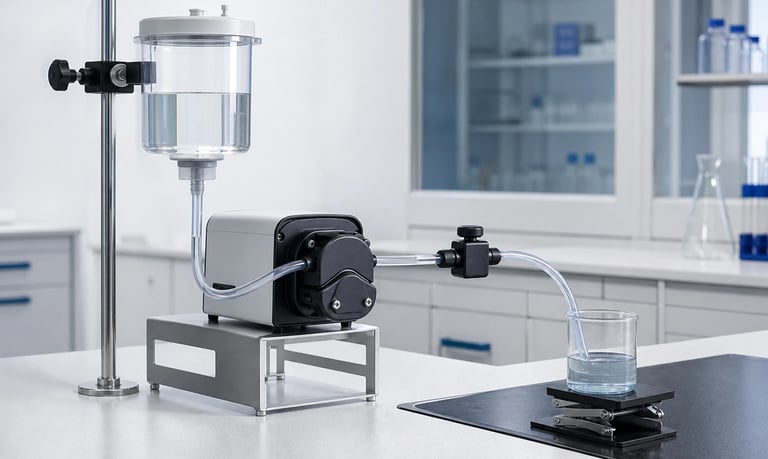
Peristaltic pump siphoning can occur when gravity creates a pressure difference across a continuous liquid path and the stopped pump, tubing, fittings, or valves do not provide a reliable fluid barrier; prevention requires controlled elevation, occlusion, shutoff hardware, routing, and fault validation.
How to Prevent Siphoning in a Peristaltic Pump System
Siphoning is unintended liquid flow driven by a difference in elevation and pressure after the pump slows or stops. In a peristaltic system, users may assume that compressed tubing always acts as a shutoff valve. That assumption can fail if occlusion is incomplete, the tube relaxes or wears, the pump head opens, a roller stops in an unfavorable position, or another part of the fluid path allows a continuous liquid column to develop.
Uncontrolled flow can create an overdose, drain a reservoir, flood equipment, contaminate a process, or allow liquid to reach a location that software cannot monitor. Prevention should rely on a defined fluid-control design and verified fault response, not only on normal pump rotation.
Confirm That the Flow Is Siphoning
Several behaviors can look like siphoning but have different causes. Observe the direction, duration, elevation, pressure, and timing of the unintended flow.
True siphoning is driven by the hydrostatic difference between the source liquid level and the discharge point through a continuous, liquid-filled path. It can continue without pump power as long as the pressure difference and liquid continuity remain sufficient.
Other possible causes include:
Backflow from a pressurized outlet toward the source
Residual pressure releasing from compliant tubing or a damper
Nozzle dripping from fluid already downstream of the pump
Thermal expansion of trapped liquid
Gravity drainage from one section of tubing
A control or motor fault that continues driving the pump
A leaking bypass, flush path, or manifold valve
Temporarily change the reservoir or outlet elevation while monitoring the flow. A strong relationship with liquid-level difference supports a siphoning diagnosis. Also verify that the motor is actually stopped and that the observed liquid is not merely stored volume leaving the outlet line.
Understand the Hydrostatic Driving Pressure
When one liquid surface is higher than another, gravity creates a pressure difference related to the vertical height and fluid density. Greater elevation difference generally creates more driving pressure.
The relevant heights can change during operation:
The source level falls as the reservoir empties
A waste container fills
A movable nozzle is raised or lowered
Tubing is routed over or under equipment panels
The product is tilted during use, cleaning, or transport
A service container is temporarily placed above the pump
Evaluate the most unfavorable credible arrangement, not only the nominal installation drawing.
A high loop in the tubing does not automatically stop a liquid-filled siphon. Once the path is primed and remains continuous, flow may pass over a point above both containers. A deliberate air break can interrupt the column, but a sealed loop alone is not a dependable anti-siphon method.
Know What Pump Occlusion Can and Cannot Do
Occlusion is the compression of the peristaltic tube between the roller and pump track. Complete occlusion can restrict forward flow and backflow while a roller is in the correct position, but shutoff performance depends on the complete pump-head design.
Influencing factors include:
Number, spacing, and parked position of rollers
Tube material, dimensions, hardness, and recovery
Pump-track geometry and head closure
Adjustable occlusion setting
Temperature and chemical exposure
Tube wear, fatigue, and compression set
Outlet pressure and hydrostatic head
Particles or residue near the compressed section
Too little occlusion can permit leakage. Too much occlusion can increase motor load, heat, tubing wear, particle generation, and risk of premature failure.
Do not tighten an adjustable head until dripping stops without checking approved limits and life effects. If the pump is expected to provide shutoff, define and test the allowed leakage rate with new and aged production tubing.
Check the Roller Parking Position
Some peristaltic pump heads always keep at least one roller fully occluding the tube. Others may have positions where compression is reduced or shared between rollers.
If the motor stops at a random angle, shutoff behavior may vary from one cycle to the next. A stepper motor, encoder, home sensor, or controlled stop sequence can park the rotor in a verified occlusion position.
Position control is useful only if:
The motor reaches and holds the intended position
Loss of power does not move the rotor
Gear backlash or external pressure cannot rotate it
Tube and pump-head tolerances preserve occlusion
The position remains safe after wear and temperature change
Test every possible stop position during early characterization. If one position allows unacceptable flow, software parking may reduce normal risk, but a separate passive shutoff may still be required for power loss, motor faults, or an opened pump head.
Control Reservoir and Outlet Elevation
Layout is the simplest place to reduce hydrostatic driving pressure. Where the process allows, position the source reservoir so its highest liquid level is not above an unprotected outlet.
Consider the complete operating sequence:
Filling a full reservoir
Dispensing into an empty and full receiving container
Moving a handheld nozzle
Removing a waste bottle
Opening a service door
Tilting or transporting the equipment
Connecting a cleaning-fluid container
Locate the pump and shutoff device with these changing levels in mind. Draw the minimum and maximum liquid surfaces on the system diagram rather than showing only container outlines.
Elevation control alone may not be practical when the outlet must move or the reservoir is replaceable. In those systems, use a reliable fluid barrier that remains effective in the worst arrangement.
Add a Normally Closed Shutoff Valve
A normally closed valve provides a separate barrier when electrical power is removed. Depending on the fluid path and application, options may include a pinch valve, solenoid valve, isolation valve, or another suitable shutoff device.
A pinch valve can close flexible tubing without adding a wetted valve chamber. Its performance depends on tube material, wall thickness, outside diameter, temperature, chemical exposure, actuator force, and tubing fatigue.
A wetted solenoid or isolation valve may provide compact shutoff but adds internal surfaces, flow resistance, retained volume, sealing interfaces, and cleaning requirements.
For any valve, verify:
Leakage in the required direction and pressure range
Closing time relative to pump shutdown
Behavior during sudden power loss
Opening pressure and effect on pump flow
Compatibility with the production fluid and cleaner
Particles, crystals, bubbles, and sticky residue
Temperature, life cycling, and long idle periods
Failure position and diagnostic coverage
Place the valve so the volume between it and the outlet cannot create an unacceptable dose after closure.
Evaluate Check and Anti-Siphon Valves Carefully
A check valve permits flow in one direction and restricts reverse flow. Standard check valves do not necessarily prevent forward siphoning because the hydrostatic pressure may open them in the intended flow direction.
An anti-siphon valve is designed to require a defined upstream pressure before forward flow begins. The pump must generate enough pressure to open it, while gravity pressure alone should remain below the opening threshold.
Selection requires balancing:
Maximum credible hydrostatic pressure
Minimum available pump pressure
Opening or cracking behavior
Flow-related pressure loss
Resealing pressure and leakage
Unit-to-unit and life variation
Fluid viscosity, temperature, and particles
Orientation and trapped-gas behavior
Do not select from one nominal cracking-pressure value. Test production samples across temperature, aging, contamination, and supply-voltage limits. Added opening pressure can reduce flow, increase pulsation, delay dose start, and store energy in flexible tubing.
Use a Controlled Air Break Where the Process Allows
An air break interrupts the continuous liquid column so gravity cannot sustain a closed siphon path. Examples include dispensing through a free-falling air gap or admitting air at a controlled high point after pumping stops.
Air gaps can be effective because they are passive and easy to inspect, but they may introduce:
Splashing or aerosol formation
Evaporation and odor release
Contamination exposure
Inaccurate drop formation
Noise
Requirements for drain or overflow management
An active vent valve can break the siphon in a closed system, but its timing and vent destination must be designed carefully. The vent may draw contamination inward, release hazardous vapor, or allow fluid to escape.
Use air breaks only when compatible with hygiene, containment, fluid stability, and process-control requirements. Validate the physical gap under all fill levels and product orientations.
Route the Outlet to Limit Gravity Drainage
Even after the siphon is broken, liquid downstream of the shutoff point may drain by gravity. Keep the unprotected outlet volume as small as practical.
Review:
Valve-to-nozzle tube length
Tube internal diameter
Low points that collect fluid
Flexible sections that expand under pressure
Nozzle elevation and orientation
Drip formation and surface tension
Drain-back after venting
Placing a valve close to the dispensing point can reduce post-stop drainage, but it may require remote wiring, add weight to a moving nozzle, or expose the valve to contamination.
If a long outlet line is unavoidable, quantify its internal and elastic stored volume. The fluid released after stop may be a dosing issue even when no true siphon continues.
Coordinate Pump and Valve Timing
The shutdown sequence affects pressure and residual delivery. Closing the valve too early can cause a pressure spike or stall the pump. Closing too late can allow an unwanted dose.
A controlled sequence may include:
Reduce pump speed near the target.
Stop forward pumping at a defined position.
Apply a short reverse movement or pressure-release step if validated.
Close the shutoff valve.
Confirm the expected pressure or flow response.
The correct order depends on valve position, fluid compliance, nozzle behavior, pump type, and whether backflow is acceptable. A reverse step can reduce dripping but may draw air or process fluid backward and can affect the next dose.
Test normal stop, emergency stop, communication loss, and immediate power removal. The design must remain safe when software cannot complete the preferred sequence.
Manage Tubing Wear and Replacement
Peristaltic tubing changes during repeated compression. Fatigue, compression set, chemical exposure, heat, and dimensional change can reduce the seal between the roller and track.
Monitor shutoff performance throughout life testing, not only flow. Include leakage or siphon checks at defined intervals and after the longest intended idle period.
Replacement criteria may be based on:
Validated operating exposure
Number of pump cycles or run time
Flow or dose drift
Leakage or loss of occlusion
Visible cracking, flattening, swelling, or hardening
Preventive-maintenance schedule
Service-life limits depend on the exact tube, pump head, speed, pressure, temperature, fluid, and duty cycle. Do not use a universal tubing-life value.
After tube replacement, verify routing, seating, head closure, occlusion, calibration, leakage, and valve operation. A new tube may behave differently from a run-in tube.
Detect Unintended Flow
Passive prevention is preferable for the primary fluid barrier, but sensing can identify a failure and limit its consequences.
Possible signals include:
Flow detected while the pump command is off
Unexpected reservoir-level decrease
Receiving-container weight increase
Pressure decay or pressure at an unexpected location
Liquid detected in a drip tray or enclosure
Mismatch between commanded and measured dose
Sensor placement and resolution must suit the smallest hazardous flow. A slowly updating level sensor may not detect a small overdose quickly enough.
Define the response to detection: close an independent valve, isolate power, stop another process, notify the user, or enter a service state. If the same controller or power source operates both the pump and shutoff valve, evaluate common-cause failures.
Design for Power Loss and Service Access
Power loss is a critical anti-siphon condition because active control may disappear while the elevation difference remains.
Verify that:
A normally closed valve returns to its safe state
Stored electrical energy cannot hold a valve open unexpectedly
The rotor does not coast to a leaking position
Manual overrides return to the correct state
Opening a service door or pump head isolates the fluid
Removing a reservoir or tube set does not release uncontrolled liquid
Consider service mistakes such as reconnecting tubing to the wrong port, leaving a clamp open, failing to latch the pump head, or installing the tube outside its track.
Mechanical keying, color-independent geometry, interlocks, and clear inspection points can reduce reliance on training alone. Interlocks should be tested for defeat, sensor failure, and power interruption as appropriate to the product risk.
Test Siphoning in the Final System
Use the actual fluid or a justified representative with relevant density, viscosity, surface tension, and wetting behavior. Water may not reproduce valve leakage, bubbles, residue, or tube response.
Test at least:
Highest source level and lowest outlet position
All credible product orientations
Fully primed and partially primed paths
New, run-in, and representative aged tubing
Minimum and maximum fluid temperature
Normal stop and every practical rotor stop position
Immediate power loss
Open, closed, failed, and contaminated valve states
Maximum idle duration
Pump-head opening and service procedures
Expected vibration, transport, and thermal cycling
Measure unintended volume or mass over a defined observation time. Record source and outlet elevations, fluid temperature, pump position, valve state, pressure, and tube condition.
Use a detection method capable of measuring slow leakage. A brief visual check may miss a flow rate that becomes significant during a long unattended idle period.
Anti-Siphon Validation Checklist
Source and outlet liquid-level extremes identified
Siphoning distinguished from backflow and stored-volume release
Hydrostatic pressure calculated or measured at worst elevation
Every rotor stop position characterized
Occlusion verified with new and aged production tubing
Adjustable head settings kept within approved limits
Normal shutdown and immediate power loss tested
Shutoff valve leakage, timing, and failure position verified
Check or anti-siphon valve opening pressure tested with system flow
Air break or vent evaluated for contamination and containment
Unprotected valve-to-outlet volume minimized and measured
First dose after reverse or venting sequence checked
Temperature, viscosity, particles, and chemical exposure included
Tube replacement and pump-head service procedures verified
Unintended-flow sensing and alarm response tested
Multiple pump, tubing, and valve samples evaluated
Long idle, vibration, transport, and orientation changes included
Acceptance limits and observation times documented
Common Anti-Siphon Mistakes
Assuming every peristaltic pump is a guaranteed shutoff valve
Confusing forward siphoning with reverse backflow
Relying on a high tubing loop without breaking the liquid column
Testing only one random rotor stop position
Increasing occlusion without checking motor load and tubing life
Using a standard check valve that opens in the siphon direction
Selecting an anti-siphon valve from nominal cracking pressure alone
Placing the shutoff valve far from the outlet
Ignoring elastic volume released after the pump stops
Validating the software stop sequence but not sudden power loss
Testing only new tubing and clean valves
Measuring leakage for too short a time
Ignoring service and reservoir-replacement configurations
Using a sensor alarm as the only fluid barrier
Frequently Asked Questions
Can a peristaltic pump siphon when it is off?
Yes. Siphoning may occur if a gravity-driven pressure difference exists and the stopped pump or another fluid-path component does not provide a complete seal.
Does a peristaltic pump need a check valve?
Not always, but the system may need a separate shutoff or anti-siphon device when unintended flow is unacceptable. A standard check valve does not necessarily prevent forward siphoning.
Will a high loop in the outlet tube stop siphoning?
Not reliably. A fully primed, sealed liquid path may continue siphoning over a high point. A controlled air break is required to interrupt the continuous column.
Can higher tube occlusion prevent siphoning?
Adequate occlusion can reduce leakage, but excessive compression increases load, heat, and wear. Use the approved setting and validate shutoff with aged tubing and worst-case pressure.
Why does liquid drip after the siphon has stopped?
Liquid remaining downstream of the shutoff point may drain, and flexible tubing or a damper may release stored volume as pressure relaxes.
What is the safest anti-siphon test?
Test the complete product at the worst source and outlet elevations with representative fluid, new and aged components, every relevant stop state, immediate power loss, and a defined leakage measurement period.
Kamoer Anti-Siphon Design Support
Kamoer can help evaluate pump-head occlusion, rotor parking, tubing, hydrostatic pressure, valve integration, fluid-path routing, stop sequences, consumable aging, and representative siphon testing for OEM peristaltic pump systems.
Related Stories
Kamoer Fluid Tech (Shanghai) Co., Ltd.
pump@kamoer.com