

How to Prevent Leaks in Micro Pump Tubing and Fittings
TROUBLESHOOTING & FAQS
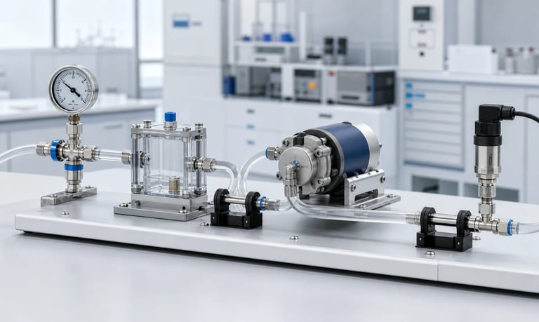
Reliable micro pump connections require tubing, fittings, seals, clamps, and assembly methods matched to positive pressure, inlet vacuum, fluid chemistry, temperature, pulsation, vibration, pull loads, cleaning, aging, and service conditions, followed by production-representative leak and retention testing.
How to Prevent Leaks in Micro Pump Tubing and Fittings
Micro pump systems use small tubing and compact fittings, so a minor dimensional or assembly error can cause liquid leakage, air entry, pressure loss, contamination, or an unstable dose. A connection that remains dry under positive pressure may still draw air inward when used on the pump inlet.
Leak prevention begins with a controlled connection design. Tube inner and outer diameter, wall thickness, hardness, fitting geometry, insertion depth, clamp force, fluid chemistry, temperature, pressure, vacuum, pulsation, vibration, and service access all affect sealing.
Visual inspection alone is not enough. The final connection must be tested in the direction, fluid, pressure, temperature, and aging condition expected in the OEM product.
Distinguish Liquid Leakage from Air Ingress
Outlet connections generally operate above atmospheric pressure. A poor seal can push liquid outward, creating visible wetness, droplets, or pressure loss.
Inlet connections often operate below atmospheric pressure. A small gap can draw air into the tubing without releasing liquid outward. The result may be:
Bubbles
Failed or slow priming
Reduced flow
Inconsistent doses
Unstable sensor readings
Loss of prime after stop
Pump noise
A connection can pass one direction and fail the other. Pressure can push a soft tube against a fitting and improve sealing, while vacuum can pull the interface open or collapse the tube.
Define whether each connection sees positive pressure, vacuum, pressure cycling, reverse flow, or all four. Select and test the joint accordingly.
Map Every Connection and Load
Create a fluid-path drawing that identifies every joint from reservoir to outlet.
For each connection, record:
Tube material, inner diameter, outer diameter, and wall thickness
Fitting type, material, and dimensions
Seal, ferrule, gasket, adhesive, or thread sealant
Clamp or retainer
Insertion depth
Normal and maximum pressure or vacuum
Temperature and fluid exposure
Pull, bending, vibration, and installation loads
Assembly and service frequency
Include filters, sensors, valves, manifolds, dampers, reservoir pickups, nozzles, and temporary service connections.
Mark connections that can release hazardous, corrosive, hot, contamination-sensitive, or expensive fluid. These may need secondary containment, detection, or a more conservative joint design.
Do not assume the pump port is the highest-pressure point. Valve switching, elevation, blockage, and line compliance can create local peaks elsewhere.
Match Tube Dimensions to the Fitting
A barbed, compression, push-to-connect, flared, or clamped fitting is designed for a specific dimensional range and tube behavior.
Confirm:
Tube inner diameter matches the barb or insert
Tube outer diameter matches ferrules, collets, and clamps
Wall thickness provides enough strength and compression
Tube roundness and tolerances are controlled
Fitting bore does not create excessive restriction
The tube can be installed without damage
A fitting that is too large may overstretch, cut, or thin the tube wall. One that is too small may not generate enough contact pressure.
Nominal tube size is not enough. Compare actual production tolerances for tube and fitting, including minimum and maximum material conditions.
Do not substitute a tube with the same inner diameter but a different outer diameter, wall thickness, hardness, or formulation without revalidation.
Select the Appropriate Fitting Type
Different connection styles suit different materials, pressures, service needs, and assembly processes.
Barbed Fittings
Barbs can provide compact retention in soft tubing. Performance depends on barb diameter, shape, number, surface finish, tube stretch, wall thickness, hardness, and clamp support.
Compression Fittings
Compression fittings use a ferrule or seal around the tube. They can provide controlled assembly when tube outer diameter and surface are suitable. Overtightening may deform or cut the tube.
Push-to-Connect Fittings
Push-in designs can simplify assembly but require compatible tube outer diameter, stiffness, surface, and cut quality. Side load or scratches can affect sealing.
Flared, Gasketed, or Threaded Connections
These may suit particular materials or service needs but add sealing surfaces, torque requirements, and potential dead volume.
Choose from verified performance and assembly control, not convenience alone. Consider how the joint is inspected, serviced, cleaned, and prevented from incorrect installation.
Prepare the Tube End Correctly
The tube end is a sealing surface. Poor cutting or handling can damage the joint before assembly.
Control:
Square cut
Approved cutting tool
No burrs, crushing, ovality, or cracks
Clean inner and outer surfaces
No particles or lubricant unless specified
Correct cut length
Traceability of tube lot
Scissors or dull blades can create an angled or compressed end. Pulling a tube from a roll can stretch it during cutting and change final length.
Avoid touching cleaned fluid-contact surfaces where contamination matters. Define whether the cut end must be inspected under magnification or with a go/no-go fixture.
Do not use unapproved solvent or heat to soften tubing for assembly. It may change material properties, leave residue, or weaken the connection.
Control Insertion Depth
Insufficient insertion reduces sealing contact and retention. Excessive insertion can bottom out, kink, block a port, enter a moving component, or place the tube on an unintended fitting feature.
Define insertion depth using:
A physical stop
A tube mark
A controlled fixture
A vision check
A measured exposed length
Account for tube stretch and relaxation. A mark applied while the tube is stretched can shift after release.
For barbed fittings, confirm which barb features must be covered. For push-to-connect fittings, verify engagement with both seal and retention mechanism.
Make the correct state easy to inspect in production. Hidden joints that depend on operator feel alone create variation.
After assembly, apply only the approved pull or proof test. Excessive inspection force can damage a good connection.
Use Clamps and Retainers Deliberately
A clamp can maintain contact pressure and improve retention, but it can also cut, creep, loosen, or distort tubing.
Possible options include spring clamps, crimp bands, ear clamps, cable-style retainers designed for fluid service, or custom features. Selection depends on tube and fitting geometry.
Define:
Clamp type and material
Location relative to the barb
Installed diameter or crimp dimension
Tool and calibration
Orientation
Reuse policy
Inspection method
Place the clamp over the intended sealing region, not beyond the fitting tip or on a transition that creates uneven compression.
Too little force permits leakage or pull-off. Too much can cut the tube, collapse the flow path, concentrate stress, or create cold flow.
Test clamp performance after temperature, chemical exposure, pressure cycling, vibration, and aging.
Avoid Excessive Tube Stretch and Side Load
Tubing pulled tightly between components applies continuous force to fittings and can reduce bore size. Thermal expansion, pump vibration, enclosure movement, and service access add more load.
Provide controlled slack and bend radius while avoiding loose loops that kink or strike the enclosure.
Check:
Axial pull at each fitting
Side load on pump ports and sensors
Minimum bend radius
Movement from pump isolation mounts
Tube routing during cover installation
Reservoir and service-module movement
Cable ties or clamps that shift the tube
A soft-mounted pump may move enough to fatigue a rigidly constrained connection. Tubing can also bypass vibration isolators and transmit pump forces into the chassis.
Validate the final routing in every product orientation and during service, not only on an open assembly bench.
Check Material Compatibility
Fluid exposure can swell, soften, harden, crack, or shrink tubing and seals. Fittings can stress crack, corrode, absorb solvent, or change dimensions.
Evaluate the exact grades with:
Product fluid
Cleaner and sanitizer
Rinse and calibration fluid
Mixed product and cleaner
Minimum and maximum concentration
Temperature
Pressure and vacuum
Continuous and long idle exposure
Wet-dry and thermal cycles
Swelling may initially tighten a joint and later soften it enough to pull off. Shrinkage or hardening can reduce sealing contact. Chemical attack may begin at a highly stressed barb or ferrule.
Static compatibility charts support screening but do not establish joint retention or dynamic sealing. Test finished connections under representative load.
Do not infer food, medical, or regulatory suitability from polymer-family names alone.
Account for Temperature and Thermal Cycling
Tube, fitting, clamp, and seal materials expand and contract at different rates. Heating can soften tubing and reduce clamp force; cooling can stiffen it and create cracking or loss of contact.
Include:
Cold startup
Hot steady operation
Heated product or cleaning fluid
Motor and enclosure heat
Storage recovery
Repeated thermal cycles
Condensation and freeze risk where applicable
Measure leakage and retention at temperature, not only after the joint returns to room conditions.
Thermal cycling can loosen threaded connections, relax clamps, move tubing, and reveal stress cracks.
If a tube is installed hot or softened for assembly, verify its final dimensions and retention after full cooling and aging. Avoid unapproved heat-assisted installation.
Account for Pressure Pulsation and Stored Energy
Positive-displacement pumps create cyclic pressure. Peak pressure may be much higher than a slow gauge reading.
Pulsation can:
Move tubing on a barb
Work a fitting interface repeatedly
Loosen a threaded or clamped joint
Fatigue tube near the connection
Create noise and vibration
Release liquid suddenly after failure
Flexible tubing and pulsation dampers store fluid energy. A failed connection can continue releasing volume after the pump stops.
Use a pressure sensor with sufficient response near critical joints. Test normal operation, startup, valve switching, restriction, and approved blockage conditions.
Reducing unnecessary restrictions or adding a validated damper may lower peaks, but a damper introduces volume, cleaning, and post-stop delivery tradeoffs.
Check Vacuum Collapse and Inlet Movement
Inlet vacuum can collapse soft tubing, pull it away from a seal, or draw air through a joint.
Risk increases with:
High viscosity
Cold fluid
Long or narrow inlet tubing
Loaded filters
Excessive suction lift
High pump speed
Poor reservoir venting
Measure vacuum at the pump inlet and inspect the tube dynamically. A tube can appear round when stopped but flatten during each pump cycle.
Use tubing with suitable wall construction and support. Avoid clamps that create a weak local oval section.
An inlet leak may show no fluid residue. Test air ingress through flow, pressure decay, bubble observation, or another validated method rather than relying only on a dry exterior.
Seal Threaded Connections Correctly
Threaded fittings can leak through the thread path, at a gasket, or from cracks caused by overtightening.
Control:
Thread type and engagement
Fitting and port material
Sealant or tape specification
Application amount and location
Assembly torque
Tool and calibration
Cure time where relevant
Reuse policy
Do not mix tapered and straight threads without the intended sealing method. A straight thread may seal on an O-ring or gasket rather than the thread itself.
Excess sealant can enter the fluid path, block a valve or nozzle, contaminate the product, or interfere with sensors. Too little may leave a leak path.
Plastic ports can crack from excessive torque, incompatible sealant, molded-in stress, or thermal cycling. Test the finished joint and inspect after aging.
Manage O-Rings and Gaskets
Static seals require the correct material, size, squeeze, groove, surface finish, lubrication, and assembly.
Check:
Exact seal grade and hardness
Groove dimensions and tolerances
Twist, cuts, nicks, or contamination
Approved lubricant
Compression and extrusion gap
Pressure direction
Temperature and chemical exposure
Reassembly limits
An O-ring can be damaged by a sharp port edge or rolled during installation. Particles across a gasket can create a leak path.
Too much compression increases assembly force and can accelerate damage. Too little leaves insufficient contact.
Use assembly fixtures and visual aids where appropriate. Do not substitute a visually similar seal material without compatibility and performance validation.
Design for Vibration and Transport
Pump reaction forces, motor imbalance, vehicle motion, shipping shock, and enclosure vibration can load connections.
Validate:
Final mounting and isolators
Tube and cable routing
Unsupported component mass
Fitting orientation
Clamp and fastener retention
Product orientation
Shipping and handling condition
A heavy valve or sensor attached directly to a small plastic pump port can create bending stress. Support the component independently while allowing necessary alignment tolerance.
After vibration or shock exposure, inspect and repeat leak, pressure, vacuum, and pull tests. A connection may remain attached yet develop a small suction leak.
Do not use tube stiffness as the only structural support for a component.
Design for Assembly and Service
A reliable prototype joint can fail in production if the assembly method is difficult to repeat.
Define:
Approved parts and revisions
Tube cut length
Insertion depth
Clamp or torque setting
Tool and fixture
Assembly order
Inspection point
Leak or proof test
Rework and reuse rules
Training and work instruction
Use error-proofing where possible. Different tube sizes should not be easily swapped. Inlet and outlet connections should be keyed or routed to reduce reversal.
For service, consider access, residual fluid, contamination, replacement kits, calibration, and post-service leak testing.
A connection intended for one-time factory assembly may not be appropriate for frequent field disconnection.
Choose an Appropriate Leak-Test Method
Leak testing may use liquid observation, pressure decay, vacuum decay, flow measurement, bubble testing, tracer gas, electrical liquid detection, or another validated method.
Select based on:
Leak direction
Fluid or gas
Required detection limit
Internal volume
Material and pressure limits
Test time
Cleanliness
Production speed
Safety and containment
Pressure-decay results depend on temperature stabilization, flexible volume, trapped gas, sensor resolution, and fixture leakage. Vacuum-decay tests must separate product leakage from fixture and permeation effects.
A water bubble test can contaminate or wet a path and may be unsuitable for some products. A dry gas test may not reproduce liquid wetting or seal behavior.
Correlate production tests with engineering tests under real fluid and operating conditions.
Test Retention as Well as Leakage
A joint can be leak-tight initially but have inadequate mechanical retention.
Evaluate as relevant:
Axial pull
Side load
Bending
Torque
Pressure impulse
Vacuum cycling
Vibration and shock
Thermal cycling
Chemical aging
Repeated connection and service
Define whether the load is applied while pressurized, at temperature, or after exposure.
Do not use an excessive pull test that damages every production joint unless the design specifically requires it. A controlled proof load can screen assembly, while destructive testing can characterize margin on separate samples.
Record the failure mode: tube pull-off, tear, clamp movement, fitting fracture, port damage, or seal leakage. The failure mode guides design improvement.
Provide Containment and Detection Where Needed
Some applications require controls beyond preventing the primary leak.
Possible measures include:
Drip tray or secondary enclosure
Drain path
Liquid sensor
Pressure or flow monitoring
Reservoir-level monitoring
Double containment
Shutoff valve
Maximum run time
Replaceable fluid module
Detection should respond before leakage creates an unacceptable consequence. Place sensors where fluid will actually collect in every product orientation.
If the pump stops after leak detection, consider siphoning, backflow, residual pressure, and stored tubing volume. Stopping the motor may not stop fluid movement.
Containment materials must be compatible with the leaked fluid and cleaner. Define safe service and disposal procedures.
Use a Structured Leak Investigation
Preserve the failed state and change one variable at a time.
Identify whether the failure is liquid leakage or suction air ingress.
Record fluid, pressure, vacuum, temperature, pump state, and time.
Photograph the joint before moving it.
Isolate adjacent joints with a verified fixture.
Repeat the leak in the original pressure direction.
Inspect tube dimensions, cut, insertion, clamp, seal, and fitting.
Compare with an approved reference assembly.
Review chemical, thermal, vibration, and service history.
Reproduce the failure with production parts and assembly methods.
Verify the corrective action across tolerances and aging.
Do not tighten, reseat, or wipe the joint before documenting evidence.
Retain the tube, fitting, clamp, seal, and surrounding components with sample identity.
Connection Validation Checklist
Every connection and pressure direction mapped
Tube material, dimensions, tolerances, and lot controlled
Fitting type, geometry, bore, material, and tolerance specified
Tube end cut, cleanliness, and length controlled
Insertion depth defined and inspectable
Clamp type, position, force, tool, and reuse rule controlled
Tube slack, bend radius, pull, and side load verified
Product, cleaner, rinse, and mixed-fluid compatibility tested
Temperature and thermal cycling included
Pressure peaks and pulsation measured
Inlet vacuum and tube collapse checked
Thread, sealant, gasket, and torque requirements documented
O-rings and grooves verified across tolerances
Vibration, shock, transport, and orientation tested
Factory and service assembly methods validated
Leak test detects both positive-pressure leakage and air ingress where needed
Retention tested after chemical, thermal, and mechanical aging
Secondary containment and detection evaluated by risk
Multiple production lots and worst dimensional combinations included
Common Connection Mistakes
Selecting fittings by nominal inner diameter only
Ignoring tube outer diameter, wall thickness, and hardness
Cutting tube ends with a dull or uncontrolled tool
Relying on operator feel for insertion depth
Placing a clamp outside the sealing region
Overtightening clamps or plastic threaded ports
Stretching tubing tightly between components
Checking positive pressure but not inlet air leakage
Testing at room temperature but operating hot or cold
Using static compatibility as proof of joint retention
Measuring average pressure but missing pulsation peaks
Supporting a heavy valve only through the pump port
Reusing one-time ferrules, clamps, seals, or damaged tubing
Wiping and tightening a failed joint before documenting it
Approving a prototype without production assembly controls
Frequently Asked Questions
Why does a pump inlet fitting draw bubbles but not leak liquid?
The running pump creates vacuum that pulls air through a small gap. When stopped or positively pressurized, the joint may seal differently and show no outward liquid leak.
Should every barbed fitting use a clamp?
Not universally. The need depends on tube and barb geometry, pressure, vacuum, material, temperature, chemistry, vibration, and retention requirements. Validate the exact connection.
Why does tubing leak after heating?
Heat can soften tubing, reduce clamp force, change dimensions, relax stress, and accelerate chemical swelling. Different materials also expand at different rates.
Can thread sealant cause pump problems?
Yes. Excess or incompatible sealant can crack plastic, contaminate fluid, block valves or nozzles, and interfere with sensors. Use the approved type, amount, location, and cure.
How should suction-side leaks be tested?
Use a validated vacuum-decay, flow, bubble, isolation, or tracer method suitable for the path. Positive-pressure testing alone may not reproduce inward air leakage.
Should connections be retested after vibration or chemical aging?
Yes. Retention and sealing can change after vibration, thermal cycling, chemical exposure, pressure pulses, and service handling even when the joint still appears intact.
Kamoer Fluid-Connection Support
Kamoer can help evaluate pump ports, tubing dimensions, fittings, clamps, pressure, vacuum, pulsation, materials, routing, assembly, and representative leak and retention tests for OEM micro pump systems.
Related Stories
Kamoer Fluid Tech (Shanghai) Co., Ltd.
pump@kamoer.com