

How to Integrate a Micro Pump into OEM Equipment
MICRO PUMP BASICS
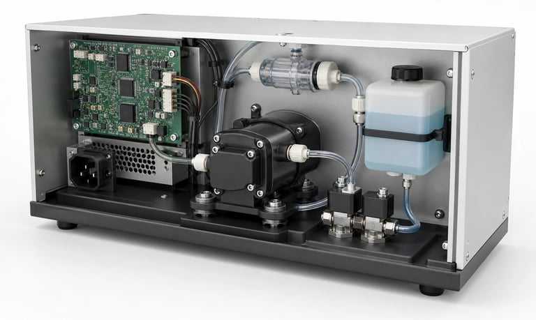
Reliable OEM micro pump integration depends on a defined operating point, compatible fluid path, secure mounting, suitable power and control, thermal and noise management, leak protection, fault handling, validation, and service access.
How to Integrate a Micro Pump into OEM Equipment
Selecting a micro pump is only the beginning of an OEM project. The final equipment must provide the pump with the correct fluid path, power, control, mounting, cooling, protection, and maintenance access. A pump that performs well on a bench can behave differently inside a compact enclosure with long tubing, restrictive valves, vibration-sensitive sensors, and limited ventilation.
Successful integration starts with a documented operating point and ends with validation in production-representative equipment.
Define the System Requirement
Create a pump requirement that covers every operating mode:
Medium composition and temperature
Minimum, typical, and maximum flow
Inlet vacuum and outlet pressure
Dose volume or circulation rate
Priming, purge, reverse, and cleaning functions
Continuous, intermittent, and peak duty cycles
Allowed noise, power, heat, and flow variation
Expected service life and maintenance concept
Include startup, low supply voltage, empty source, blocked line, loaded filter, shutdown, transport, and storage. For gas systems, define flow at the required vacuum or pressure. For liquid dosing, define the minimum controllable dose and allowed variation.
Select the Pump Around the Operating Point
Do not select from maximum free flow alone. Filters, valves, tubing, fittings, elevation, sensors, mixers, heat exchangers, and nozzles move the pump to a different operating point.
Use relevant pump curves or sample test data to confirm flow at the expected resistance. Include margin for component tolerances, temperature, medium viscosity, filter loading, wear, and supply variation.
Excessive oversizing can create short run times, poor low-flow control, additional noise, current peaks, heat, and unnecessary restriction. The normal operating point should remain within a controllable and validated part of the pump's range.
Design the Fluid Path
Keep tubing as short and direct as the equipment permits. Avoid sharp bends, kinks, tension, unsupported weight, and fittings that reduce internal diameter unexpectedly.
Review:
Inlet and outlet tube diameter
Total tube length and elevation
Minimum bend radius
Filter and valve pressure loss
Dead volume and drainability
Bubble or condensate traps
Siphoning and residual pressure
Cleaning and replacement access
Use compatible tubing retention and fittings. A connection must remain secure across pressure, vacuum, temperature, vibration, aging, and service cycles.
For suction paths, small leaks can admit air without producing visible liquid leakage. Test the assembled inlet path rather than only the pump.
Verify Wetted-Material Compatibility
List every wetted material in the pump, tubing, seals, fittings, valves, filters, reservoirs, and sensors. Evaluate the production medium together with cleaners, sanitizers, calibration fluids, mixed waste, and foreseeable contaminants.
Compatibility depends on concentration, temperature, pressure, exposure time, and mechanical stress. Also consider adsorption, permeation, extractables, outgassing, swelling, hardening, residue, and particle shedding where product performance is sensitive.
General compatibility charts support screening but do not replace representative testing. Regulatory or food-contact suitability must be supported for the exact component configuration and intended market.
Plan Mechanical Mounting
Mount the pump on a stable structure with access to fasteners, tubing, and connectors. Account for motor torque, vibration, shock, transport, and the mass of attached lines.
Rigid mounting can transmit noise into panels and tanks. Resilient mounts may reduce structure-borne vibration but must not allow excessive motion, tube fatigue, connector stress, or contact with neighboring parts.
Provide clearance for:
Motor and pump movement
Tube installation and replacement
Ventilation
Connector latches
Manufacturing tolerances
Tool access
Drip containment and drainage
Validate mounting in the final enclosure rather than on an isolated plate.
Design the Electrical Supply
Confirm rated voltage, allowed range, startup current, operating current at the actual pressure, and behavior during brownout or power interruption. Wire size, connector rating, driver capacity, protection, and power-supply margin must support worst-case operation.
Motor switching can introduce electrical noise. Review grounding, cable routing, shielding, suppression, and separation from sensitive sensor or communication lines according to the pump and system design.
Provide suitable protection against reverse polarity, overcurrent, stalled operation, and unintended restart where required. Do not assume that every pump includes internal protection.
Choose the Control Interface
Control may use switched power, PWM, analog commands, stepper pulses, speed feedback, or digital communication. Use only interfaces supported by the specific pump or controller.
Useful software functions include:
Soft start
Fast prime followed by controlled operation
Recipe-based speed and time
Reversible purge or suck-back
Closed-loop flow, pressure, vacuum, or level control
Maximum run-time limits
Empty-source, blockage, leak, or failed-prime detection
Runtime and maintenance logging
Timed operation does not guarantee a fixed volume. Voltage, pressure, viscosity, temperature, air, and wear can alter delivery. Calibrate or add feedback when required by the process.
Manage Heat and Ventilation
Pump temperature depends on motor load, speed, duty cycle, pressure condition, supply voltage, ambient temperature, and enclosure airflow. Nearby electronics, heaters, insulation, and sealed housings can raise the local temperature.
Test inside the final enclosure until temperature stabilizes. Include the worst expected restriction, simultaneous loads, maximum ambient temperature, and reduced ventilation caused by dust or installation conditions.
Keep tubing and temperature-sensitive fluid away from hot surfaces. Confirm that mounting materials, wires, connectors, and nearby components tolerate the measured temperature.
Reduce Noise and Vibration
Evaluate airborne noise, tonal content, clicking, and structure-borne vibration across the full speed and pressure range. Enclosure panels, reservoirs, brackets, and rigid tubes can act as sound radiators.
Possible controls include resilient mounting, flexible tube sections, adequate clearance, suitable speed selection, gradual acceleration, and avoiding structural resonance. A muffler or damper may help in gas systems but adds resistance and internal volume.
Measure noise in the completed product and verify that mitigation does not reduce cooling, serviceability, or mechanical security.
Protect the Equipment from Leaks
Route liquids away from electronics, batteries, connectors, vents, and hot surfaces. Use secondary containment, drip shields, drainage, absorbent or sensing elements, and protected connectors according to risk.
Validate loose fittings, cracked tubes, blocked outlets, overfilled tanks, siphoning, power loss, and pump or valve leakage. Fault logic should place the equipment in a safe state without creating additional pressure or spills.
Gas systems may require controlled exhaust, leak testing, ventilation, or containment depending on the gas. Hazardous applications require documented components and system-level risk controls.
Design for Manufacturing and Service
Production assembly should be repeatable and easy to inspect. Use defined tube lengths, controlled routing, keyed connectors, torque specifications, retention features, and visual or automated checks.
Avoid relying on tube color alone for identification. Prevent crossed inlet and outlet lines, reversed polarity, pinched tubing, missing filters, and incorrect pump variants.
Make consumable tubing, filters, traps, and pump modules accessible. Define whether service requires calibration, leak testing, flushing, firmware reset, or replacement of adjacent parts.
Build a Fault-Diagnostics Strategy
Useful signals include flow, pressure, vacuum, level, liquid presence, bubbles, motor current, speed, temperature, and run time.
Combine signals where practical to distinguish:
Empty reservoir or open inlet
Inlet leak
Loaded filter or blocked outlet
Failed priming
Worn tube or valve
Liquid ingress in a gas path
Stalled or disconnected motor
Sensor failure
Establish thresholds using representative good units, component tolerances, aged parts, and real faults. Avoid thresholds based on a single prototype.
Validate Before Production
Full medium and environmental range
Minimum and maximum flow, pressure, vacuum, and dose
Minimum and maximum supply voltage
Startup, prime, normal, purge, clean, and shutdown modes
New and loaded filters
Empty, blocked, leaking, and power-loss faults
Continuous, intermittent, and peak duty cycles
Thermal stabilization in the final enclosure
Noise and vibration in production mounting
Drip, siphon, condensation, and leakage behavior
New and aged tubing, valves, diaphragms, and seals
Transport, shock, orientation, and storage
Manufacturing tolerances and multiple pump samples
Service replacement and post-service verification
Common Integration Mistakes
Selecting from free-flow data only
Finalizing the enclosure before testing pump clearance
Ignoring pressure loss from small fittings and filters
Using unsupported control signals or PWM conditions
Measuring current without the real operating load
Evaluating noise on an open bench
Allowing tubing to carry pump weight or vibration
Routing potential leaks above electronics
Setting fault thresholds from one prototype
Omitting service and recalibration procedures
Frequently Asked Questions
Where should an OEM micro pump be mounted?
Use a stable, accessible location with appropriate ventilation, tube routing, leak protection, and vibration control. Validate mounting inside the final enclosure.
How much flow margin should an OEM pump have?
Margin should cover known tolerances and operating variation without creating control, noise, power, or heat problems. Determine it from pump curves and representative system tests.
Can PWM control any DC micro pump?
No. Confirm that the specific motor, driver, and electronics support the proposed PWM voltage, frequency, and duty range.
How should pump faults be detected?
Combine available flow, pressure, vacuum, current, speed, liquid, level, and temperature signals. Establish thresholds from representative normal and fault tests.
When should the pump be tested in the final enclosure?
As early as possible, then again with production-representative hardware. Mounting, airflow, tubing, power, and enclosure resonance can materially change performance.
Kamoer OEM Integration Support
Kamoer can help evaluate the operating point, pump type, fluid path, materials, mounting, power, control, noise, thermal conditions, fault detection, validation, and production integration for OEM micro pump projects.
Related Stories
Kamoer Fluid Tech (Shanghai) Co., Ltd.
pump@kamoer.com