

How to Detect an Empty Reservoir in a Micro Pump System
TROUBLESHOOTING & FAQS
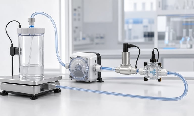
Reliable empty-reservoir detection combines a sensor or process signal with validated thresholds, timing, plausibility checks, and a safe response because low level, an exposed pickup, inlet leak, blocked vent, bubbles, viscous fluid, blockage, and sensor failure can produce overlapping pump symptoms.
How to Detect an Empty Reservoir in a Micro Pump System
An empty source can cause missed doses, air entry, loss of prime, pump overheating, product waste, unreliable sampling, and damage in pumps that require liquid for lubrication or cooling. The safest detection method depends on the reservoir, pump type, fluid, dose size, environment, and consequence of continued operation.
No single indirect signal identifies every empty condition. Low flow can also result from a blocked filter, inlet leak, viscous fluid, closed valve, worn tube, or failed motor. Motor current can rise, fall, or remain similar depending on pump mechanism and fluid path.
Reliable detection combines the most direct available measurement with timing, plausibility checks, and a defined response and recovery process.
Define What "Empty" Means
The reservoir does not need to contain zero liquid before the system should stop.
Possible empty definitions include:
Liquid below the pickup opening
Minimum usable volume reached
Remaining volume insufficient for the next dose
Level below a warning threshold
Air detected in the inlet
Required flow cannot be maintained
Container mass below a defined value
Flexible bag fully collapsed
Maximum expected withdrawal reached
Distinguish warning, refill, stop, and service thresholds. A product may warn early, complete the current dose, then prevent the next cycle.
Account for residual liquid that cannot be reached because of reservoir shape, tilt, pickup geometry, surface tension, or bag folds.
Define the consequence of an incorrect decision. A false empty alarm reduces availability; a missed empty condition may create an incorrect dose or damage.
Map Reservoir and Pickup Behavior
Understand how the source empties in every product orientation.
Record:
Reservoir shape and capacity
Minimum and maximum fill
Pickup location and opening
Usable and residual volume
Venting or bag collapse
Product orientation and tilt
Agitation and return flow
Foam, particles, and settling
Refill or replacement procedure
A rigid reservoir, collapsible bag, cartridge, bottle, and open tank require different sensing strategies.
The liquid surface may not be flat during motion or pump operation. A narrow or irregular reservoir can show large height changes for small volumes.
Test the actual container and pickup rather than inferring usable volume from a CAD model alone.
Use Direct Level Sensing Where Practical
Level sensing can directly identify liquid position without relying on pump behavior.
Possible methods include:
Float switch
Capacitive sensing
Optical sensing
Ultrasonic or time-of-flight sensing
Conductive electrodes
Hydrostatic pressure
Mechanical displacement
External noncontact sensing
Selection depends on fluid conductivity, dielectric properties, optical clarity, foam, bubbles, vessel material, geometry, temperature, coating, and cleanliness.
A point sensor provides one threshold. A continuous sensor estimates level over a range but requires calibration to reservoir geometry.
Ask what happens with residue on the sensor, condensation, an empty but wet wall, tilted liquid, foam, or a changed fluid formulation.
Direct sensing is useful, but it should still be checked against pump flow and plausibility where empty failure has significant consequences.
Evaluate Float and Mechanical Level Switches
Floats and mechanical switches can provide simple threshold detection.
Check:
Fluid density and buoyancy
Mounting orientation
Minimum vessel dimensions
Hysteresis
Mechanical travel
Sticking from residue or particles
Vibration and shock
Material compatibility
Wire and seal integrity
Cleaning access
A float can remain high because of foam, surface tension, deposits, or mechanical interference. It may also oscillate near the threshold as the pump pulses or product moves.
Use software debounce or mechanical damping only after understanding the real level dynamics.
Test minimum and maximum temperature, fluid density, contamination, and product orientation. A switch tested in water may not float or release the same way in another liquid.
Consider whether the float creates a dead volume or traps product.
Evaluate Capacitive and Optical Level Sensors
Capacitive sensors detect changes in dielectric properties. They can operate through some nonmetallic vessel walls but are influenced by wall thickness, fluid, residue, humidity, nearby structures, grounding, and calibration.
Optical point sensors detect a change in light behavior when a surface contacts liquid. They can be affected by coating, bubbles, foam, color, opacity, condensation, and ambient light.
For either method, test:
Every fluid formulation
Clean and coated surfaces
Full and empty but wet states
Temperature and humidity
Vessel tolerances
Sensor position
Bubbles and foam
Cleaning cycles
Cable and electromagnetic environment
Do not assume a noncontact sensor eliminates compatibility concerns. The vessel wall, adhesive, mounting, and product residue still influence performance.
Define startup self-test and behavior when the sensor becomes disconnected or saturated.
Use Reservoir Weight or Load Cells
Weighing the reservoir provides a direct measure of remaining mass when the container and mounting allow it.
Potential advantages include:
Continuous remaining-quantity estimate
Independence from fluid color or optical clarity
Ability to detect consumption over time
Support for dose verification
Challenges include:
Product movement and vibration
Tube and cable forces on the reservoir
Variable container tare
Mounting stress
Temperature drift
Multiple fluids or components on one scale
User contact or refill force
Fluid density when converting mass to volume
Flexible tubing can support part of the reservoir weight and create level-dependent error. Route connections to minimize changing force.
Calibrate tare and span with production containers and mounting. Define how partial refill, container replacement, and spilled fluid are handled.
Use filtering that preserves a timely empty decision without following every pump pulse.
Use Flow Measurement
A flow sensor can detect when pump command no longer produces expected flow.
Compare:
Commanded flow or dose
Measured flow
Response delay
Minimum detectable flow
Pump startup and prime behavior
Sensor zero and drift
Bubbles
Pressure and viscosity
Low flow is not unique to an empty source. It can indicate a blocked inlet or outlet, failed valve, collapsed tube, motor stall, high viscosity, or sensor fouling.
Use supporting signals such as inlet pressure, reservoir level, motor current, and bubble detection.
For short doses, sensor response may be too slow to prevent one incomplete dispense. The controller may need to reject the dose, re-prime, or notify the process.
Do not allow a low flow reading to drive unlimited pump speed or run time.
Use Pressure or Vacuum Signals
Inlet pressure can change when the source empties, but the direction and magnitude depend on reservoir design.
With a vented rigid reservoir, an exposed pickup may draw air and inlet vacuum can fall or become unstable. Before exposure, vacuum may rise as liquid level drops or a filter loads.
With a sealed rigid reservoir and blocked vent, vacuum may rise even though liquid remains.
With a flexible bag, vacuum may rise when the bag folds or stops collapsing.
Therefore, pressure thresholds should distinguish:
Empty pickup
Vent blockage
Inlet restriction
Air leak
Viscous fluid
Filter loading
Combine pressure with flow or level where possible. Use time patterns and pump state, not one instantaneous value.
Place the sensor near the pump inlet and validate its range, response, bubble behavior, and port cleanliness.
Use Bubble Detection
An optical bubble detector or other gas-liquid sensor can identify air entering the inlet after the pickup is exposed.
Advantages include direct detection near the failure mechanism. Limitations include:
Bubbles from inlet leaks
Dissolved gas release
Foam
Transparent-tube requirements
Fluid color or opacity
Tube dimensional variation
Sensor alignment
Residue and condensation
Define the smallest gas segment that matters and the detection response time.
A bubble signal may arrive after part of an incorrect dose has already been delivered. The controller must decide whether to stop, mark the dose invalid, close a valve, or re-prime after refill.
Test known bubble sizes, speeds, fluids, tube lots, temperatures, and orientations.
Do not treat all detected air as an empty reservoir without checking for leaks and outgassing.
Use Motor Current with Caution
Motor current reflects torque and electrical behavior, not liquid level directly.
An empty condition can produce different signals:
Lower load when liquid resistance disappears
Similar load because tube compression dominates
Higher or irregular load from failed priming or bubbles
Changed load only at certain speeds
Current is also affected by:
Outlet pressure
Inlet restriction
Viscosity and temperature
Peristaltic occlusion
Diaphragm valve behavior
Motor wear
Supply voltage
Driver control
Use current as one feature in a fault model, not a universal empty detector.
Record command, speed, voltage, current, flow, pressure, and reservoir state across multiple pump samples. Validate thresholds at cold startup and pressure extremes.
Use Run Time or Pump Motion as an Estimate
The controller can estimate remaining volume by integrating calibrated pump output or counting doses, revolutions, steps, or operating time.
This approach can be low cost but accumulates error from:
Initial fill uncertainty
Refill amount
Tube wear
Pressure and viscosity
Bubbles
Failed doses
Calibration drift
Manual fluid removal
Leakage or siphoning
Power or data loss
Use estimation as a prediction or plausibility signal unless accuracy is validated for the full process.
Reconcile the estimate after reservoir replacement, refill, or a direct level measurement.
Protect stored totals from corruption and interrupted writes. Define behavior when the estimate is missing or inconsistent.
Do not assume motor motion equals delivered liquid.
Combine Signals for Better Diagnosis
Signal combinations can distinguish overlapping faults.
Examples:
Low level plus low flow supports an empty-source diagnosis
High inlet vacuum plus low flow suggests restriction or vent blockage
Bubble detection plus normal motor speed supports air entry
Low flow plus high outlet pressure suggests downstream blockage
No flow plus low motor speed suggests drive or stall fault
Weight decrease without commanded flow suggests leakage or siphoning
Build the logic from measured data rather than assumptions.
Use fault persistence, state machines, and plausibility windows to avoid false decisions during startup, priming, valve switching, or natural pulsation.
Where consequences are significant, use independent signals that do not share the same failure mode.
Document the diagnostic confidence and which faults remain indistinguishable.
Define Warning and Stop Thresholds
Set thresholds based on usable volume and process needs.
A warning threshold should allow enough time or remaining volume for:
Completing a safe operation
Alerting the user
Preparing replacement fluid
Preventing air from entering a sensitive path
Avoiding an incomplete next dose
Include sensor tolerance, reservoir variation, tilt, fluid movement, pickup geometry, pump delay, and production variation.
Use hysteresis or state control so a level near the threshold does not repeatedly change status.
Do not set hysteresis so wide that the system resumes without enough fluid.
For continuous processes, define how much volume can be delivered between detection and pump stop.
Test the threshold with minimum and maximum dose size and pump speed.
Define the Safe Response
The correct response depends on pump type, fluid, and process risk.
Possible actions include:
Stop the pump
Complete or abort the current dose
Close a shutoff valve
Mark the dose invalid
Prevent automatic retry
Reduce speed
Move to a safe position
Notify the user or upstream controller
Log the event
Request reservoir replacement
Stopping the motor may not stop siphoning, backflow, or stored-volume release.
Some peristaltic pumps can tolerate limited dry running, while other pumps rely on liquid for cooling or lubrication. Use exact supplier data and validation.
Do not repeatedly prime an empty source without a maximum time, attempt count, and waste or overflow control.
Plan Refill and Recovery
After refill or container replacement, the system may contain air and require re-priming.
Define:
How replacement is detected
Whether the user confirms the action
Prime speed and timeout
Valve positions
Waste destination
Bubble-clear criterion
First-dose handling
Calibration or tare update
Alarm reset
Prevent a partially connected or incorrectly oriented reservoir from being accepted.
For load-cell systems, capture the new tare and expected fill range. For level sensors, confirm the signal changes through a plausible sequence.
For disposable bags or cartridges, control part identity and connection.
Test refill after complete empty, early warning, power loss, and interrupted prime.
Handle Sensor Failure
Every empty-detection method has failure modes.
Consider:
Sensor disconnected
Short circuit
Frozen output
Drift
Coating or fouling
Blocked pressure port
Stuck float
Bubble detector misalignment
Load-cell overload
Corrupted remaining-volume estimate
Communication loss
Define valid range, update timing, plausibility, startup self-test, and diagnostic coverage.
A frozen normal reading can be harder to detect than an out-of-range failure. Compare the signal with pump operation and expected consumption.
Choose a safe fallback. The system may stop, limit operation, require service, or use a secondary estimate depending on risk.
Do not bypass a failed sensor indefinitely without a controlled degraded mode.
Account for Pump Type
Peristaltic Pumps
Tube compression creates much of the motor load even when no liquid is present, so current may change little. Flow or bubble sensing is often more direct.
Dry running may be mechanically possible for some configurations, but tube heat, speed, pressure, and service life still require review.
Diaphragm Liquid Pumps
An empty source introduces gas into the chamber. Prime may be lost, valves may respond differently, and the pump can fail to rebuild liquid pressure.
Some internal components may rely on fluid conditions. Use supplier-approved dry-run limits.
Gas Pumps
An "empty reservoir" may instead be loss of sample gas, disconnected line, or open inlet. Pressure, flow, gas composition, and process state are more relevant than liquid level.
Match the detection model to the exact pump and medium.
Validate across Fluid and Environmental Conditions
Sensor behavior changes with fluid and environment.
Test:
Minimum and maximum temperature
Viscosity and density range
Foam and bubbles
Fluid color and conductivity
Particles and residue
Full, low, and tilted reservoir
Clean and loaded filters
Minimum and maximum voltage
Cold startup and thermal steady state
Vibration and transport
Humidity and condensation
Capacitive and optical sensors can shift with fluid formulation or residue. Float buoyancy changes with density. Pressure and flow thresholds shift with viscosity and temperature.
Use production containers, pickups, tubing, electronics, software, and mounting.
Include multiple pump, reservoir, and sensor samples.
Build a Representative Empty Test
Empty the real reservoir through normal operation while recording:
Actual remaining mass or volume
Level-sensor output
Pump command and speed
Flow or dose
Inlet and outlet pressure
Motor voltage and current
Bubble signal
Fluid and sensor temperature
Warning and stop state
Delivered volume after detection
Repeat for continuous flow and intermittent dosing. Test full-to-empty, partially filled, partially refilled, tilted, and flexible-container fold conditions.
Introduce non-empty faults such as blocked vent, inlet restriction, air leak, loaded filter, viscous fluid, and sensor failure to measure false diagnosis.
Verify safe stop, valve behavior, alarm, logging, refill, priming, and first valid dose.
Preserve raw synchronized data for threshold tuning.
Empty-Detection Checklist
Empty, warning, refill, and stop states defined
Usable and residual volume measured in all orientations
Reservoir, pickup, vent, and flexible-container behavior mapped
Direct level methods evaluated with fluid and residue
Float, capacitive, optical, conductive, or other sensor limits tested
Load-cell mounting, tare, tube force, vibration, and temperature validated
Flow detection range, delay, bubbles, and false causes reviewed
Inlet pressure patterns distinguished for empty, restriction, and vent blockage
Bubble detection tested with leaks and outgassing
Motor current used only with supporting evidence
Run-time or pump-motion estimate includes drift and refill uncertainty
Multiple signals combined where consequences require it
Warning, stop, hysteresis, and remaining-volume margins validated
Safe response handles siphoning and stored fluid
Refill, prime, alarm reset, and first-dose sequence defined
Sensor disconnection, frozen output, drift, and fouling tested
Pump-specific dry-run behavior reviewed
Fluid, temperature, orientation, vibration, and production variation included
Real and false empty conditions tested end to end
Common Empty-Detection Mistakes
Defining empty as zero physical liquid
Using total reservoir capacity instead of usable volume
Testing one upright orientation only
Assuming a flexible bag always collapses completely
Using motor current as the only signal
Treating low flow as proof of empty source
Ignoring blocked vent and loaded-filter faults
Detecting bubbles without distinguishing inlet leaks
Integrating pump run time as if motion equals delivered volume
Setting thresholds from one prototype
Stopping the motor without controlling siphoning or stored volume
Retrying prime indefinitely
Ignoring sensor coating, frozen data, and disconnected states
Testing detection but not refill and first-dose recovery
Frequently Asked Questions
What is the best way to detect an empty pump reservoir?
The best method depends on container, fluid, dose, and risk. Direct level or weight sensing is often useful, while flow, pressure, bubble, and current signals can provide confirmation and fault diagnosis.
Can motor current detect an empty reservoir?
Sometimes it contributes, but current also changes with pressure, viscosity, temperature, occlusion, voltage, and wear. It should not be assumed to provide universal empty detection.
Can a flow sensor detect an empty source?
It can detect missing output, but blockage, leaks, bubbles, pump faults, and sensor fouling can also reduce flow. Combine it with other signals where needed.
How early should a low-level warning occur?
Set it early enough to complete the intended safe action and prevent an incomplete next dose, including sensor tolerance, pickup residual, tilt, process delay, and replacement time.
What should the pump do after empty detection?
It may stop, close a valve, reject the dose, log a fault, and request refill. The response should also control siphoning, stored pressure, dry-run exposure, and automatic retry.
How should refill recovery be tested?
Test container replacement, connection, sensor reset, priming, bubble clearance, waste handling, first-dose verification, power interruption, and incorrect or partial refill.
Kamoer Empty-Reservoir Detection Support
Kamoer can help evaluate pump behavior, reservoir and pickup design, flow and pressure signals, bubbles, motor current, dry-run limits, fault logic, and representative empty and refill tests for OEM systems.
Related Stories
Kamoer Fluid Tech (Shanghai) Co., Ltd.
pump@kamoer.com