

How to Design a Fluid Path for OEM Equipment
MICRO PUMP BASICS
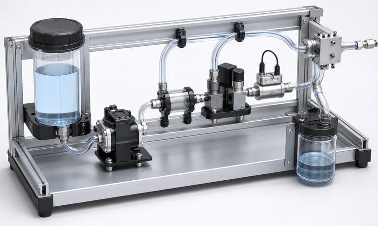
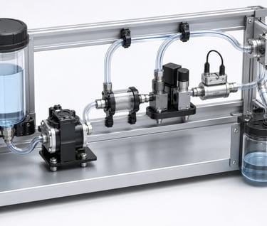
Reliable OEM fluid path design depends on a defined process, controlled pressure loss, compatible tubing and components, bubble and siphon management, low dead volume, effective cleaning, leak protection, validation, and serviceable routing.
How to Design a Fluid Path for OEM Equipment
An OEM fluid path connects reservoirs, pumps, valves, filters, sensors, process chambers, nozzles, and waste containers. Its layout determines the pressure the pump must overcome, the time required to prime or purge, the amount of trapped fluid, the risk of bubbles and leaks, and how easily the equipment can be cleaned and serviced.
A good pump cannot compensate for a poorly designed fluid path. Design should begin with the process requirement, then account for every component and operating state before tubing and fittings are released for production.
Map Every Operating State
Draw the complete fluid circuit and show the direction of flow during:
Initial fill and priming
Normal transfer, circulation, or dosing
Reverse flow or suck-back
Rinsing and cleaning
Drainage and waste transfer
Standby and long idle periods
Reservoir or cartridge replacement
Service and component replacement
Power loss and fault conditions
Identify which valves are open, which pump operates, and where pressure, vacuum, air, and residual liquid are present in each state. A path that works during normal operation may siphon, cross-flow, or trap pressure after shutdown.
Define the Hydraulic Requirement
Specify minimum, typical, and maximum flow together with inlet vacuum and outlet pressure. Include fluid density, viscosity, temperature, particles, gas content, and required response time.
Pressure loss comes from straight tubing, elevation, bends, fittings, valves, filters, sensors, manifolds, mixers, heat exchangers, and nozzles. It changes with flow and viscosity and can rise as a filter loads or deposits form.
Estimate each contribution, then measure the assembled circuit. Select the pump using the required flow at the real pressure condition rather than maximum free flow.
Choose Tubing Diameter and Length
Small internal diameter reduces internal volume but can greatly increase pressure loss. Large tubing reduces resistance but occupies more space, holds more fluid, takes longer to prime, and may increase waste during flushing.
Choose diameter by balancing:
Required flow and pressure loss
Prime and response time
Dose or sample volume
Bubble movement
Fluid viscosity and particles
Available fittings and pump ports
Bend radius and routing space
Cleaning and replacement requirements
Keep runs as short and direct as practical. Avoid sudden reductions, unnecessary adapters, tight bends, kinks, tube tension, and unsupported tubing weight.
Select Tubing and Wetted Materials
List every material that contacts the process medium, including pump components, tubing, seals, valves, fittings, filters, sensors, reservoirs, adhesives, and lubricants.
Evaluate production fluids, cleaners, sanitizers, calibration fluids, mixed waste, and foreseeable contaminants under actual concentration, temperature, pressure, and exposure time.
Look beyond visible chemical attack. Swelling, hardening, permeation, adsorption, extractables, outgassing, odor, taste, particle shedding, and loss of elastic recovery may affect performance.
Regulatory or food-contact suitability must be supported for the exact component configuration and intended use. A material-family name alone does not establish compliance.
Design Reliable Connections
Connections must remain sealed under pressure, vacuum, temperature changes, vibration, transport, and service cycles. Match tube dimensions and hardness to the fitting design.
Possible connection methods include barbed fittings, compression fittings, threaded ports, push-to-connect fittings, clamps, and welded or bonded joints. Each has different assembly controls, dead volume, retention, and service implications.
Define insertion depth, clamp position, thread seal method, torque, and inspection criteria. Avoid side loads that can crack ports or pull tubing from fittings.
For suction paths, a connection can admit air without leaking liquid outward. Include assembled-path leak testing.
Place the Pump and Reservoir
Reservoir height relative to the pump affects inlet pressure, priming, siphoning, and residual volume. Keep the inlet path short and airtight, especially when the pump must lift liquid.
Reservoir pickup geometry should remain submerged across fill level, tilt, acceleration, and vibration without trapping excessive unusable fluid. Venting must allow liquid to leave without creating unwanted pressure or contamination.
Place the pump where leakage can be contained and service parts remain accessible. Avoid routing likely leaks over electronics, batteries, hot surfaces, or optical components.
Use Valves Intentionally
Valves may isolate reservoirs, prevent backflow, switch channels, control pressure, or stop dripping. They also add pressure loss, internal volume, leakage paths, and surfaces that can trap residue.
For each valve, define:
Normal and fault position
Opening and closing pressure
Flow capacity and pressure loss
Internal leakage and external leakage
Wetted materials
Response time
Cleanability and drainability
Behavior without power
Check cross-flow when multiple fluids share a manifold. Validate valve timing with pump acceleration and fluid compliance to avoid pressure spikes or drawing vacuum against a closed path.
Size and Monitor Filters
Filters protect pumps, valves, sensors, and nozzles, but resistance increases as they collect material. Define filter medium, pore size, area, chemical behavior, clean pressure loss, end-of-service pressure loss, and replacement interval.
Place a filter where it protects sensitive components without making priming or service unnecessarily difficult. Confirm whether it can trap air or retain liquid.
Test with representative contamination and a loaded filter. Pressure, vacuum, flow, runtime, or motor-current monitoring may support maintenance alerts when thresholds are established from system data.
Manage Bubbles and Gas
Air may enter during priming, reservoir replacement, through inlet leaks, or by outgassing. Bubbles compress, alter dose volume, interrupt sensors, create noise, and delay response.
Route tubing to avoid high points that trap gas unless a deliberate bubble trap is installed. Use gradual rises toward a vent or separator where appropriate. Avoid reservoir returns that continuously aerate the fluid.
Possible controls include bubble sensors, degassing, separators, controlled priming, low-shear routing, and software timeouts. Validate with the actual fluid because surface tension, viscosity, and dissolved gas affect bubble behavior.
Control Siphoning, Dripping, and Residual Pressure
Gravity can move fluid after the pump stops when the source is above the outlet. Tube recovery, compressed gas, elastic chambers, check-valve leakage, and nozzle wetting can also cause post-run flow.
Controls may include pump placement, path elevation, shutoff valves, appropriate check valves, pump reversal or suck-back, controlled deceleration, and nozzle design.
Test full and nearly empty reservoir levels, all equipment orientations, warm and cold fluid, power interruption, and long standby. A small residual drop may be important relative to a micro dose.
Minimize Dead Volume and Carryover
Dead volume increases prime time, reagent consumption, cleaning volume, sample delay, and carryover. Common sources include oversized tubing, tees, valve cavities, sensor chambers, filters, dampers, and unused manifold branches.
Remove unnecessary branches and avoid pockets that cannot drain or flush. When dead volume cannot be eliminated, quantify it and incorporate it into purge, cleaning, and calibration procedures.
Validate carryover using the actual analytical or product-quality method. A visually clear rinse does not prove that the path is clean.
Design for Cleaning and Drainage
Define whether the path is single-use, replaceable, manually cleaned, flushed in place, or sanitized automatically. Include every cleaning fluid, concentration, temperature, contact time, and disposal step.
Design for:
Adequate cleaning flow through every branch
Minimal residue traps
Drainable low points
Controlled venting
Access to replaceable parts
Safe collection of waste
Verification after cleaning
The cleaning procedure must be compatible with the pump, tubing, valves, filters, sensors, and adhesives—not only the process fluid.
Protect Against Leakage and Condensation
Use secondary containment, drip trays, drainage channels, protected connectors, and leak detection according to risk. Ensure containment still works when equipment is tilted or installed unevenly.
Gas paths and chilled liquid lines may create condensation. Insulation, heated lines, water traps, hydrophobic filters, drainage, and moisture sensing may be required.
Fault logic should stop pumps and close or open valves to a defined safe state. Avoid responses that trap hazardous pressure or worsen a leak.
Make Routing Manufacturable and Serviceable
Define tube lengths, bend radii, clips, separation, labels or identifiers, and installation order. Use routing features that prevent pinching when covers close and avoid abrasion against sharp edges.
Key connectors and fittings where possible. Do not rely on tube color alone to prevent misconnections. Provide tool access and replacement clearance without requiring unrelated assemblies to be disturbed.
After service, specify leak, prime, flow, pressure, calibration, and cleaning checks as appropriate.
Validation Checklist
Every operating, cleaning, standby, and fault state
Minimum and maximum flow, pressure, vacuum, and temperature
Full tubing length, diameter, fittings, valves, filters, and sensors
Actual process, cleaning, and waste fluids
New and loaded filters
Minimum and maximum reservoir level and elevation
Empty-line priming and long-idle restart
Bubbles, inlet leaks, outgassing, and foam
Drip, siphon, backflow, cross-flow, and residual pressure
Dead volume, response time, and carryover
Cleaning effectiveness and drainability
Upright, tilted, transported, and stored orientations
Blockage, loose tube, cracked container, and power loss
Manufacturing tolerances and multiple assemblies
Service replacement and post-service verification
Common Fluid-Path Mistakes
Selecting tube diameter by available space alone
Ignoring pressure loss from fittings and loaded filters
Adding valves without checking dead volume and cleanability
Placing high points where bubbles collect
Routing suction tubing with avoidable leaks and restrictions
Overlooking siphoning during power loss
Using general compatibility data as final approval
Allowing leakage to reach electronics
Creating branches that cannot flush or drain
Finalizing routing before production and service trials
Frequently Asked Questions
How should tubing diameter be selected?
Balance pressure loss, internal volume, response time, viscosity, particles, available fittings, and pump capability. Verify with the assembled system.
Should a filter be installed before or after the pump?
Placement depends on what needs protection, pump tolerance, priming, pressure loss, bubble trapping, and service access. Validate the chosen arrangement with representative loading.
How can bubbles be removed from a fluid path?
Use airtight inlet connections, suitable routing, controlled priming, separators, vents, degassing, or bubble detection as appropriate. Test with the real fluid.
What causes siphoning after the pump stops?
Source-to-outlet elevation, an open continuous liquid column, valve leakage, and residual pressure can continue moving liquid. Path layout, valves, or suck-back may help.
How can dead volume be measured?
Use component geometry as an estimate, then measure the actual volume required to replace or recover fluid under the real priming and purge sequence.
Kamoer OEM Fluid-Path Support
Kamoer can help evaluate flow, pressure loss, tubing, fittings, valves, filters, bubbles, materials, cleaning, leakage, pump placement, testing, and OEM fluid path design.
Related Stories
Kamoer Fluid Tech (Shanghai) Co., Ltd.
pump@kamoer.com