

How to Choose a Pump for Intermittent Dosing
PUMP SELECTION GUIDES
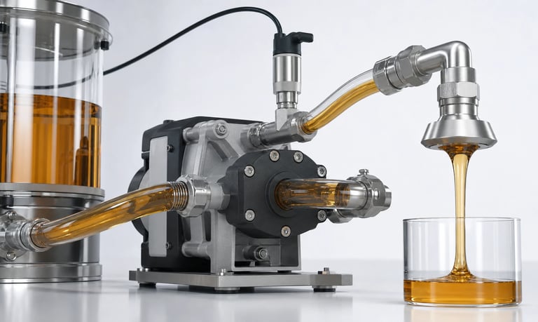
Reliable intermittent dosing depends on a pump matched to the minimum and maximum dose, available dispensing time, fluid properties, pressure, priming, startup and stop behavior, control resolution, calibration, idle conditions, and cycle life.
How to Choose a Pump for Intermittent Dosing
Intermittent dosing systems deliver discrete volumes separated by idle periods. Applications include reagent addition, flavor and chemical dosing, lubrication, cleaning agents, calibration fluids, nutrients, and laboratory automation.
The challenge is not only achieving an average flow rate. Each dose includes startup delay, acceleration, fluid-path compliance, bubble behavior, stopping response, and possible post-run dripping. A suitable intermittent dosing pump must be selected and calibrated around the complete dose cycle.
Define the Dosing Profile
Document:
Minimum, typical, and maximum dose volume
Allowed dispensing time
Doses per minute, hour, day, and product life
Required accuracy and repeatability
Adjustable or fixed dose range
Idle time between doses
Maximum burst sequence
Forward, reverse, prime, and purge functions
Also define fluid temperature, reservoir level, inlet elevation, downstream pressure, and allowable delay before the process uses or measures the dose.
The lifetime number of starts can be more important than total run hours. Include relay, connector, motor, tube, valve, and driver cycles in the reliability plan.
Calculate the Active Flow Range
Required active flow is the dose volume divided by the available pump run time. Calculate this for the minimum and maximum doses.
Avoid selecting a pump so large that the minimum dose requires an extremely short pulse. Motor startup, control latency, valve response, and residual drops can then represent a large fraction of the commanded volume.
A pump that is too small may require an unacceptable dispensing time or operate near its pressure limit. Choose a range that leaves enough command duration or motor steps for repeatable control while meeting cycle-time requirements.
Select the Pump Technology
Peristaltic Pumps
Peristaltic pumps keep fluid inside replaceable tubing. They can suit intermittent dosing where fluid isolation, self-priming, reversible motion, and tube replacement are valuable.
Dose depends on tube dimensions, occlusion, speed, pressure, temperature, and wear. Tube recovery after stopping can affect dripping or suck-back. Calibration and preventive tube replacement are required.
Diaphragm Liquid Pumps
Diaphragm liquid pumps may suit intermittent transfer or dosing when the required volume, flow, and pressure match the pump. The fluid contacts the chamber, diaphragm, valves, seals, and ports.
Valve opening, bubbles, particles, deposits, and viscosity can affect startup and small-dose consistency. A simple transfer pump may require external valves, sensing, or feedback for tighter dosing.
Stepper and Other Metering Pumps
Stepper-driven peristaltic, syringe, piston, piezoelectric, or other metering technologies may provide useful motion or volume resolution for some applications. Fluid delivery still depends on pressure, leakage, compliance, materials, and calibration.
No pump type is universally best for every dose range or fluid.
Characterize the Fluid
Provide chemical composition, concentration, viscosity, density, surface tension, volatility, temperature, particles, foaming, and crystallization tendency. Include rinsing, cleaning, and mixed waste fluids.
Viscosity affects fill behavior and pressure loss. Surface tension and nozzle wetting affect drop formation. Volatile fluids can create bubbles or evaporative concentration changes. Crystallizing fluids may obstruct valves and nozzles during idle periods.
Verify every wetted material under actual concentration, temperature, pressure, and exposure time. Also consider adsorption, permeation, extractables, and carryover where dose quality is sensitive.
Evaluate Startup Behavior
The pump does not always deliver its steady flow immediately after the command begins. Startup may include electrical delay, motor acceleration, tube deformation, valve opening, pressure buildup, and compression of trapped gas.
Measure individual short doses rather than estimating them from steady-state flow. Test:
First dose after priming
First dose after a short idle
First dose after a long idle
Doses at minimum and maximum voltage
Cold and warm fluid
Full and nearly empty reservoir
If the first dose differs from later doses, the control sequence may need a prime, pre-charge, discard, or feedback step.
Control Stopping, Dripping, and Siphoning
Fluid may continue moving after the motor stops because of gravity, residual pressure, tube recovery, valve leakage, fluid inertia, or nozzle wetting. Even one drop can be significant relative to a micro dose.
Possible controls include:
Controlled deceleration
Pump reversal or suck-back
A compatible shutoff valve
Suitable check-valve placement
Optimized nozzle geometry
Tube-occlusion adjustment where supported
Fluid-path elevation management
Each measure has limitations. A valve adds pressure loss and dead volume, while excessive suck-back can draw air or process fluid into the line. Validate the complete system.
Manage Priming and Bubbles
Air may enter after reservoir replacement, through inlet leaks, or from outgassing. Bubbles compress and occupy fluid-path volume, so commanded pump movement may deliver less liquid than expected.
Use airtight inlet connections, suitable reservoir pickup geometry, controlled priming, bubble or liquid sensing, and maximum prime timeouts where appropriate.
Validate dose performance after empty-line startup, refill, tilt, long idle, and temperature changes. A water test may not reproduce the actual fluid's wetting, foam, or dissolved-gas behavior.
Account for Back Pressure
Filters, valves, tubing, elevation, sensors, mixers, and dispensing nozzles create resistance. Pressure can change flow, valve behavior, tube expansion, motor load, and post-run dripping.
Calibrate with the final outlet and all downstream components installed. Test minimum and maximum expected pressure, including loaded filters or partially restricted nozzles.
If process pressure changes during the dose, measure its effect on individual delivered volumes rather than only average flow.
Choose the Control Method
Timed DC Operation
A fixed speed and run time are simple but sensitive to startup threshold, voltage, pressure, viscosity, temperature, and wear.
PWM or Analog Speed Control
Variable speed can support fast prime, controlled dispense, and slow finish profiles. Confirm the supported electrical interface and usable speed range for the exact pump.
Step Control
Stepper motion provides defined increments and profiles. Steps command motor movement, not guaranteed liquid volume, so calibration and stall consideration remain necessary.
Closed-Loop Dosing
Weight, flow, pressure, level, drop, or optical feedback can verify delivery or terminate a dose. Include sensor resolution, delay, fluid compatibility, and added pressure loss.
Use limits for maximum run time, pressure, speed, and accumulated error so a failed sensor cannot create an excessive dose.
Build a Dose Calibration
Calibrate the complete system using the production fluid, tubing, fittings, nozzle, control profile, pressure, temperature, and supply voltage.
Measure:
Individual minimum doses
Typical and maximum doses
Repeated dose sequences
First dose after different idle periods
Startup and shutdown contribution
Forward and reverse delivery
New and aged tubing or valves
Different reservoir levels and fluid lots
Use a measurement method with sufficient resolution. Average volume across many cycles can hide unacceptable dose-to-dose variation.
Define recalibration after pump, tube, valve, nozzle, firmware, or fluid changes.
Evaluate Peak Duty and Thermal Load
Intermittent operation can still produce high thermal load when doses occur in rapid bursts. Repeated startup current and short off-times may prevent the motor and driver from cooling.
Define the worst burst profile, not only the daily average. Test inside the final enclosure at maximum ambient temperature, worst pressure, and minimum and maximum voltage.
Monitor pump, motor, driver, fluid, and enclosure temperature until the burst sequence and recovery pattern are stable.
Plan for Idle Time
During idle periods, fluid may evaporate, separate, crystallize, settle, cure, or diffuse through tubing. Valves and wetted surfaces can stick, and pressure may equalize or build.
The system may require recirculation, agitation, capping, flushing, drainage, pre-dose priming, or a maximum allowed idle time. Validate restart after the longest expected storage and standby conditions.
Keep software clocks, maintenance counters, and power-loss recovery consistent with the fluid's idle-state requirements.
Monitor Dosing Faults
Useful signals include flow, weight, pressure, liquid presence, bubbles, reservoir level, motor current, speed, and run time.
Fault logic should distinguish:
Empty reservoir
Failed priming
Inlet leak
Blocked nozzle or loaded filter
Worn tube or failed valve
Unexpected dripping or siphoning
Stalled or disconnected motor
Sensor error
Establish thresholds using representative pumps, component tolerances, aged parts, and real fault tests.
Validate Cycle Life
Life testing should reproduce dose volume, speed profile, pressure, fluid, temperature, idle duration, starts, cleaning, and maintenance.
Track dose mean and variation, prime time, current, temperature, noise, leakage, dripping, and component condition. Use multiple samples and inspect the actual wear mechanism.
An accelerated test is useful only when increased frequency, speed, pressure, or temperature does not create a different failure mechanism from real use.
Validation Checklist
Minimum, typical, and maximum dose
Individual-dose accuracy and repeatability
Full dispensing-time range
First dose after short and long idle
Production and cleaning fluids
Minimum and maximum temperature and viscosity
Full and nearly empty reservoir
Empty-line priming, bubbles, and inlet leaks
Minimum and maximum pressure
Drip, siphon, suck-back, and valve timing
Minimum and maximum supply voltage
Worst burst sequence and enclosure temperature
New and aged tubing, valves, seals, and nozzles
Blockage, empty-source, sensor, and power-loss faults
Lifetime starts and representative maintenance
Common Selection Mistakes
Selecting from average flow alone
Making the minimum dose an extremely short pulse
Estimating short doses from steady-state flow
Ignoring first-dose behavior after idle
Calibrating without the final nozzle and pressure
Treating motor steps as guaranteed liquid volume
Averaging many doses and hiding individual variation
Overlooking post-run dripping and siphoning
Using daily average duty instead of the worst burst
Life-testing run hours without the real start count
Frequently Asked Questions
Which pump is best for intermittent dosing?
The choice depends on dose range, fluid, pressure, control resolution, priming, dripping, idle behavior, and maintenance. Peristaltic, diaphragm, and other metering pumps each have different strengths and limits.
How is the required dosing flow calculated?
Divide dose volume by the available active dispensing time, then confirm that startup and stopping effects do not dominate the smallest dose.
Why is the first dose after idle different?
Pressure relaxation, evaporation, bubbles, valve sticking, tube recovery, deposits, or fluid separation can change the first cycle.
Can pump run time alone provide an accurate dose?
It may be repeatable under stable conditions, but pressure, voltage, viscosity, temperature, air, and wear can change delivery. Calibration or feedback may be required.
How should intermittent pump life be tested?
Reproduce the actual number of starts, dose profile, fluid, pressure, temperature, idle time, burst operation, cleaning, and maintenance across multiple samples.
Kamoer Intermittent Dosing Support
Kamoer can help evaluate dose range, pump type, fluid, pressure, priming, control resolution, dripping, calibration, idle behavior, burst duty, fault detection, and cycle-life testing.
Related Stories
Kamoer Fluid Tech (Shanghai) Co., Ltd.
pump@kamoer.com