

How to Choose a Pump for Continuous Operation
PUMP SELECTION GUIDES
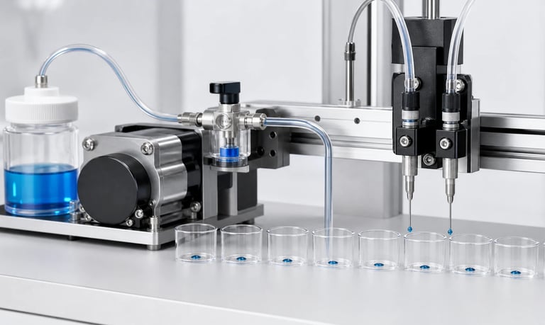
Reliable continuous pumping depends on a micro pump matched to the real flow and pressure operating point, medium, motor, thermal environment, control, wear mechanisms, monitoring, maintenance plan, and representative life validation.
How to Choose a Pump for Continuous Operation
Continuous operation places different demands on a micro pump than occasional transfer or short dosing cycles. Motor heat, bearing load, diaphragm or tubing fatigue, valve wear, fluid temperature, filter loading, and deposits can accumulate over long run times.
A pump should not be described as suitable for continuous duty simply because it can run without stopping during a short bench test. Selection must be based on the real flow and pressure operating point, enclosure temperature, medium, control method, maintenance strategy, and representative life testing.
Define What Continuous Operation Means
Continuous duty may mean uninterrupted 24-hour operation, long daily runs, or repeated cycles with very short off-times. Document the actual profile:
Hours per day and days per year
Maximum uninterrupted run time
Starts, stops, and reversals
Normal and peak speed
Minimum and maximum flow
Inlet vacuum and outlet pressure
Ambient and medium temperature
Planned maintenance interval
Acceptable downtime and fault response
Include startup, cleaning, purge, standby, blocked-line, loaded-filter, and low-voltage conditions. A pump may experience its highest electrical or mechanical stress outside normal steady operation.
Select at the Real Operating Point
Filters, valves, tubing, nozzles, sensors, elevation, and process pressure create resistance. A pump's free-flow value does not show its flow, current, or temperature in the installed system.
Use the relevant performance curve to identify the required flow at actual inlet vacuum and outlet pressure. Test the full circuit with clean and expected end-of-service restrictions.
Avoid operating continuously at an extreme edge of the pump range unless the specific model and system have been validated there. Appropriate margin should cover tolerances, temperature, wear, fluid variation, and voltage without creating excessive size, power, noise, or control difficulty.
Compare Pump Technologies
Peristaltic Pumps
Peristaltic pumps isolate the fluid inside replaceable tubing and can support continuous circulation or transfer when the tube, speed, pressure, temperature, and pump head are suitable.
The tube is repeatedly compressed and is a predictable wear component. Flow may drift as it fatigues. Continuous use therefore requires representative tube-life testing, preventive replacement, and recalibration.
Diaphragm Liquid Pumps
Diaphragm liquid pumps can provide compact transfer or pressure. Long-term performance depends on the diaphragm, valves, chamber materials, motor, pressure, medium, and temperature.
Particles, crystals, deposits, and bubbles can affect valve sealing. Continuous testing should include expected contamination and cleaning conditions.
Diaphragm Gas Pumps
Diaphragm gas pumps can provide ongoing sampling flow, vacuum, or pressure. Evaluate flow at the required operating point, together with humidity, filter loading, condensation risk, leakage, pulsation, and enclosure temperature.
Do not assume a gas pump can tolerate continuous liquid ingestion.
Choose the Motor and Drive System
Brushed DC motors are simple and economical but contain brushes and commutators that wear. Brushless motors remove brush wear and may offer speed feedback or integrated control, but bearings, electronics, and pump mechanisms still have finite life.
Stepper motors provide controlled motion and can suit peristaltic or metering applications. Driver current, speed, acceleration, torque margin, and holding behavior affect heat and reliability.
Motor type alone does not establish continuous-duty capability. Review documentation for the exact pump and verify it at the real load, voltage, temperature, and control conditions.
Manage Thermal Conditions
Continuous motor and fluidic losses create heat. Temperature depends on speed, pressure or vacuum, voltage, motor efficiency, mounting, enclosure airflow, nearby heat sources, and ambient conditions.
Test the pump inside the final enclosure until temperature stabilizes. Measure motor, pump head, driver electronics, fluid, mounting surface, and nearby component temperatures where relevant.
Include:
Maximum ambient temperature
Minimum and maximum supply voltage
Worst expected restriction
Simultaneous equipment loads
Dust or installation effects on ventilation
Warm cleaning or process fluids
Do not rely only on an open-bench temperature. A small sealed enclosure can produce a substantially different result.
Evaluate the Medium and Wetted Materials
Continuous exposure can reveal compatibility problems that are not visible in a short immersion or pumping test. Provide the full chemical composition, concentration, temperature, pressure, particles, humidity, and cleaning fluids.
Inspect for swelling, hardening, cracking, corrosion, permeation, adsorption, extractables, residue, and loss of elastic recovery. Mechanical cycling can accelerate material change.
Validate the pump, tubing, seals, valves, fittings, filters, and sensors together. General compatibility data is only a starting point.
Account for Wear and Flow Drift
Wear mechanisms depend on pump type and may include:
Peristaltic tube fatigue
Diaphragm flexing
Valve-seat wear or deposits
Motor brush wear
Bearing wear
Seal or fitting relaxation
Filter loading
Particle abrasion
Measure flow, pressure, current, temperature, noise, leakage, and visible condition throughout life testing. Do not evaluate only whether the pump still rotates.
Define acceptable drift and the point at which maintenance, recalibration, or replacement is required.
Plan the Control Strategy
Running at the lowest suitable speed may reduce noise and some wear mechanisms, but an excessively low command can produce unstable motion, poor valve operation, insufficient cooling, or inadequate torque.
Control options include fixed operation, variable speed, pressure or flow feedback, scheduled flushing, and load-dependent adjustment. Confirm that PWM, analog, stepper, or digital commands are supported by the exact pump electronics.
Soft start can reduce electrical and pressure transients. Avoid rapid cycling unless the pump and process are designed for it, because repeated starts may create more stress than steady operation.
Monitor Pump Health
Useful signals include:
Flow
Inlet vacuum and outlet pressure
Motor current or speed
Pump and enclosure temperature
Filter differential pressure or runtime
Leakage or moisture
Vibration and noise trends
Monitoring can help distinguish a loaded filter, inlet leak, worn tube, failed valve, blocked line, empty source, or motor fault.
Set thresholds using multiple representative pumps, normal variation, aged parts, and real fault simulations. A single prototype cannot define robust limits.
Design for Maintenance
Continuous systems need a maintenance concept before release. Decide which parts are consumable, their access method, expected replacement interval, and required checks after service.
Make tubing, filters, traps, valves, and pump modules accessible.
Use keyed connectors and controlled tube routing.
Record run hours, cycles, faults, and replacements.
Verify flow, pressure, vacuum, leakage, and calibration after service.
Provide containment for fluid released during replacement.
Set maintenance intervals from representative life data with appropriate risk consideration, not from a universal service-life assumption.
Consider Redundancy and Safe Degradation
Applications that cannot tolerate a pump interruption may require redundancy, bypass, stored capacity, alarmed shutdown, or a planned service window.
Two pumps do not automatically create a reliable redundant system. Check valves, isolation, standby aging, shared power, shared filters, software, and common fluid paths can create common failure modes.
Periodically test standby components if they are part of the risk-control strategy. Define whether a failed pump can be replaced without contaminating or stopping the process.
Build a Representative Life Test
Life testing should reproduce the important stresses of actual use:
Production medium and cleaning fluids
Real flow, pressure, vacuum, and speed
Maximum enclosure and fluid temperature
Minimum and maximum voltage
Filter loading and deposits
Startup, stop, reverse, and cleaning cycles
Representative mounting and vibration
Fluid replenishment and long idle conditions
Use multiple samples and record performance at planned intervals. Inspect failed and completed units to identify the actual wear mechanism.
Accelerated testing can be useful only when the acceleration method preserves the relevant failure mechanism. Excessive temperature, speed, pressure, or chemical concentration may create an unrealistic failure.
Validation Checklist
Exact continuous and peak duty profile
Required flow at real vacuum and pressure
Production, cleaning, and waste media
Minimum and maximum voltage
Maximum ambient and enclosure temperature
New and loaded filters
Startup, stop, reverse, and fault cycles
Continuous thermal stabilization
Flow and pressure drift over time
Current, speed, noise, vibration, and leakage trends
New and aged tubing, diaphragms, valves, and seals
Blockage, empty source, inlet leak, and power loss
Maintenance replacement and recalibration
Multiple samples and production tolerances
End-of-test teardown and failure analysis
Common Selection Mistakes
Treating a short uninterrupted test as continuous-duty proof
Selecting from free-flow data only
Ignoring enclosure temperature
Assuming brushless means unlimited life
Testing with water instead of the actual medium
Measuring operation but not performance drift
Omitting loaded-filter and blockage conditions
Setting maintenance intervals without life data
Accelerating tests until the failure mechanism changes
Adding a standby pump without checking common failures
Frequently Asked Questions
What is a continuous duty micro pump?
It is a pump whose specific model and configuration are rated and validated for the defined uninterrupted or high-duty operating profile at the required load and environment.
Is a brushless pump always suitable for continuous use?
No. Brushless motors remove brush wear, but bearings, electronics, diaphragms, valves, tubing, heat, and the operating point still determine suitability.
Can a peristaltic pump run continuously?
It may, when the pump head, tubing, speed, pressure, temperature, and maintenance plan are validated. Tubing remains a wear component.
How should continuous-pump temperature be tested?
Run the pump at the worst representative load inside the final enclosure until temperatures stabilize, including maximum ambient conditions and nearby heat sources.
How is service life determined?
Use representative testing across multiple samples while tracking flow, pressure, current, heat, leakage, noise, and component condition. Define failure from process requirements.
Kamoer Continuous-Duty Pump Support
Kamoer can help evaluate operating point, pump technology, motor, medium, thermal conditions, control, monitoring, maintenance, life testing, and OEM integration for continuous-duty micro pump applications.
Related Stories
Kamoer Fluid Tech (Shanghai) Co., Ltd.
pump@kamoer.com