

How to Calibrate a Peristaltic Pump for Dosing
MICRO PUMP BASICS
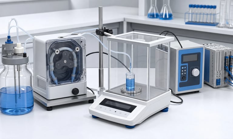
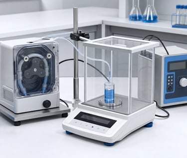
Reliable peristaltic pump calibration links a defined motor command to measured delivered mass or volume under controlled fluid, tubing, pressure, temperature, and timing conditions, then verifies accuracy, repeatability, range, drift, stored coefficients, and recalibration triggers.
How to Calibrate a Peristaltic Pump for Dosing
Peristaltic pump calibration creates a measured relationship between a pump command and the liquid delivered. The command may be run time, motor revolutions, encoder counts, stepper steps, or another controlled motion value.
Calibration is necessary because theoretical tube volume does not fully predict real output. Tube dimensions, roller geometry, occlusion, tube recovery, inlet refill, outlet pressure, fluid viscosity, temperature, bubbles, acceleration, and wear all affect each dose.
A useful calibration procedure does more than adjust one sample to one target. It defines the test conditions, measures repeatability, calculates a controlled correction, verifies the operating range, stores traceable data, and identifies when recalibration is required.
Define the Dosing Requirement
Write the performance requirement before choosing the calibration method.
Define:
Target dose or dose range
Allowed accuracy error
Allowed repeatability variation
Time available for dispensing
Number and timing of repeated doses
Fluid identity and density
Temperature and viscosity range
Inlet and outlet pressure range
Reservoir-level range
First-dose and post-idle requirements
Whether priming or purge volume is part of the process
Measurement units and rounding rules
Accuracy and repeatability are different. A pump can deliver nearly the same wrong dose every time, which is repeatable but inaccurate. Calibration can correct a stable average error, but it cannot correct unpredictable bubbles, slipping tubing, unstable pressure, or lost motor motion.
State whether the requirement applies to every individual dose, the average of a batch, or cumulative volume over time. The correct test and acceptance calculation depend on that choice.
Freeze the Calibration Configuration
Calibration belongs to a defined hardware, software, and process configuration. Record:
Pump and pump-head model and revision
Motor, gearbox, driver, and feedback
Tubing part number, dimensions, lot, and condition
Occlusion or pump-head setting
Inlet and outlet tubing, fittings, valves, filters, and nozzle
Reservoir geometry and liquid level
Fluid identity, lot, preparation, and age
Firmware and calibration-algorithm version
Speed, acceleration, deceleration, and reversal settings
Valve timing and post-dose sequence
Measurement equipment and calibration status
Changing tube size, pump head, nozzle, pressure, fluid, driver settings, or dispense profile can invalidate the result.
Use the production fluid path whenever possible. A short open outlet can reduce pressure and produce a calibration that does not represent the final product.
Choose Mass or Volume Measurement
Gravimetric Calibration
Gravimetric calibration measures delivered mass with a balance. It is often practical for small liquid doses because balances can provide useful resolution and automated data output.
If the required result is volume, convert mass using fluid density at the relevant temperature:
Delivered volume = delivered mass / fluid density
Density must use compatible units. Do not assume water density for another liquid or ignore concentration and temperature when they materially affect the conversion.
Control evaporation, air currents, vibration, splashing, static charge, and liquid contact between the nozzle and receiving vessel. Taring should follow a consistent procedure.
Volumetric Calibration
Volumetric calibration measures liquid volume directly with suitable calibrated glassware, a pipette system, a flow standard, or another verified method.
Meniscus reading, wetting, drainage time, trapped bubbles, graduation resolution, and operator technique can limit accuracy. Very small doses may be difficult to assess visually.
Choose the method whose uncertainty is small enough relative to the dosing requirement. The measurement system must be better than the distinction the calibration is expected to make.
Check the Measurement System
Before calibrating the pump, verify the reference equipment and setup.
For a balance, review:
Resolution, repeatability, linearity, and capacity
Calibration or verification status
Stable, level, low-vibration support
Draft protection
Sample rate and settling behavior
Tare method
Evaporation and static control
Data capture and rounding
For a volumetric or flow reference, review:
Range and resolution
Calibration fluid and current status
Temperature sensitivity
Required orientation
Pressure loss and internal volume
Bubble sensitivity
Response time and sampling
Run a repeatability check using a stable reference or controlled mass where appropriate. A noisy measurement can make a stable pump appear inconsistent and can produce an incorrect correction factor.
Document the estimated measurement uncertainty and confirm that it supports the acceptance decision.
Prepare the Pump and Fluid Path
Install the approved tube without twist, stretch, or incorrect tension. Confirm that the pump head is fully closed and that tubing guides, clamps, and fittings match the production configuration.
Prime the path using the validated sequence. Remove bubbles from the tube, pump head, valves, sensors, and nozzle. Confirm that the reservoir is vented and the pickup remains submerged.
Condition the fluid and equipment to the defined temperature. Record fluid temperature near the pump, not only room temperature.
If a tube run-in procedure is required, define:
Fluid
Speed
Pressure
Duration or number of revolutions
Temperature
Rest period before calibration
Do not invent an informal run-in to make results look stable. The same procedure must be practical and controlled in production or service.
After preparation, check for leaks, tube movement, abnormal motor current, incomplete refill, and post-stop dripping.
Select a Representative Calibration Dose
Calibration at one dose can work when the command-to-output relationship is sufficiently linear and operating conditions are stable. Short doses often require additional points.
Choose a calibration dose that:
Falls within the normal operating range
Produces enough measured mass or volume for good resolution
Includes representative acceleration and stopping
Does not overflow or approach balance capacity
Contains enough pump motion to reduce partial-cycle sensitivity where possible
If the product uses a wide range, calibrate or verify at low, middle, and high doses. The minimum dose may be dominated by motor startup, backlash, tube compression, nozzle wetting, and valve timing. A high-dose calibration factor may not predict it accurately.
Use the same dispensing profile that production will use. Calibrating at steady speed and then dosing with a rapid acceleration and suck-back sequence creates a different system.
Collect Repeated Calibration Doses
Do not calculate a coefficient from a single dispense. Repeated measurements reveal spread, drift, bubbles, and setup problems.
A typical sequence should define:
Prime and stabilize according to the approved method.
Tare or record the receiving vessel.
Deliver one dose using the production command.
Allow the specified settling or drainage time.
Record mass or volume without selective rounding.
Repeat for the planned number of doses.
Record temperature, pressure, motor command, and any abnormal event.
The number of repetitions should be chosen from measurement uncertainty, process variation, quality requirements, and failure risk. There is no universal count that suits every product.
Keep individual results. Reporting only the average can hide an unacceptable spread or a first-dose problem.
If one dose is rejected because of a known event such as an external spill, document the reason. Do not discard results merely because they differ from the target.
Calculate the Calibration Factor
The form of the factor depends on the pump command.
For a time-controlled pump:
Flow calibration factor = measured delivered volume / commanded run time
For a stepper or encoder-controlled pump:
Volume-per-count factor = measured delivered volume / commanded steps or counts
If the initial command produced an average delivered dose different from the target, a simple proportional correction may be calculated as:
New command = old command × target dose / measured average dose
This correction assumes sufficiently linear behavior near the calibration point. Verify the new command with fresh repeated doses. Do not repeatedly apply corrections without checking whether the system is stable.
Use full internal calculation precision and apply defined rounding only when creating the final command. For very small doses, command quantization may prevent an exact numerical target. Select the nearest validated command and report the achievable result.
Evaluate Accuracy, Repeatability, and Drift
After each run, evaluate at least:
Mean delivered dose
Error relative to target
Minimum and maximum result
Spread or standard deviation where required
Trend with dose number
First dose compared with later doses
Cumulative delivered amount
Use the statistical method approved for the product and quality system. State whether error is expressed in absolute units or as a percentage.
Percentage error can appear very large at tiny targets even when the absolute difference is small. Conversely, a small percentage at a large dose may still exceed the process limit. Define both in the units that matter to the application.
Plot or inspect results in time order. A stable average can hide a gradual upward or downward trend caused by tube run-in, fluid warming, evaporation, filter loading, or pressure change.
Calibration should proceed only after random variation and drift are within controllable limits.
Calibrate Across the Operating Range
One coefficient may not describe the full range. Test low, normal, and high commands as well as relevant speed and pressure combinations.
Nonlinearity can result from:
Motor acceleration and deceleration
Gearbox backlash
Partial roller cycles
Stepper microstep behavior
Minimum DC motor speed
Incomplete tube refill at high speed
Tube expansion under pressure
Valve opening and nozzle wetting
Post-stop drainage or suck-back
Possible calibration models include a single factor, separate ranges, a lookup table, or a fitted curve. Use the simplest model that meets the verified requirement.
Avoid overfitting a small dataset. Additional coefficients cannot reliably compensate for unmeasured bubbles, unstable pressure, tube movement, or changing fluid properties.
Verify intermediate points that were not used to build the model.
Control Rotor Position and Partial Cycles
Peristaltic output varies through a rotor revolution. Very short doses may include different parts of the roller waveform depending on the start position.
Position-aware strategies may include:
Dispensing complete rotor revolutions
Starting from a known home position
Counting stepper steps or encoder pulses
Parking the rotor at a defined position
Using the same acceleration and stopping profile
Open-loop step counting assumes the motor does not lose steps. A DC motor requires sufficient position feedback if exact angular movement matters.
Even with known rotor position, fluid output can vary with tube recovery, pressure, bubbles, and nozzle behavior. Test real doses rather than relying on geometry alone.
If the controller cannot know position, use a dose and averaging method that reduces sensitivity to partial cycles, or apply direct feedback where justified.
Account for Pressure and Fluid-Path Compliance
Outlet pressure can expand flexible tubing, compress trapped gas, change tube slip, and store liquid. Part of the pump command may build pressure before liquid exits the nozzle.
After the pump stops, stored energy may release an additional drop. A shutoff valve, damper, long tube, or flexible component changes the timing.
Calibrate with:
Production tubing length and diameter
Final fittings, filters, valves, sensors, and nozzle
Minimum and maximum outlet pressure
Production elevation difference
Realistic clean and loaded filter states
Validated valve and suck-back timing
Measure the dose at the actual delivery point. Calibration at the pump outlet may not include downstream storage and dripping.
For systems with changing pressure, determine whether separate calibration, pressure compensation, or closed-loop measurement is required.
Account for Temperature and Viscosity
Temperature can change both the fluid and the tube. Many liquids become more viscous when cold, increasing inlet resistance and slowing tube refill. Tubing flexibility, recovery, dimensions, and occlusion also change with temperature.
Calibrate at a controlled reference temperature, then verify the minimum and maximum operating temperatures. Record:
Fluid temperature near the pump
Pump-head and enclosure temperature
Fluid viscosity where relevant
Cold-start and stabilized results
Flow or dose during warm-up
If error changes predictably, validated temperature-specific coefficients may help. Do not assume a linear correction without enough data.
Temperature compensation cannot correct trapped bubbles, a blocked filter, tube wear, or fluid formulation changes. The system should detect or limit conditions outside the calibrated range.
Manage Tube Variation, Run-In, and Wear
The tube is a dimensional and elastic pumping component. Output can vary between lots, after installation, during early use, and throughout service.
Evaluate:
Multiple production tube samples and lots
New, run-in, and representative aged tubes
Tube dimensions and hardness tolerances
Chemical and temperature exposure
Pump-head closure and occlusion
Tube movement and retention
Flow and dose drift during life testing
Decide whether calibration belongs to each pump, each replaced tube, each production lot, or a validated common configuration. The answer depends on required accuracy and measured variation.
If the user replaces tubing, provide a controlled installation, priming, calibration, and verification procedure. A coefficient stored for the previous tube may not remain valid.
Define service limits using representative testing. Do not rely on a universal tubing lifetime.
Calibrate the First Dose and Idle Behavior
The first dose after idle can differ because the tube relaxes, fluid cools or settles, pressure decays, liquid drains, or the nozzle changes wetting state.
Test after:
Short pauses between normal doses
The longest routine idle period
Overnight or longer shutdown where relevant
Cleaning and tube replacement
Power cycling
Reservoir replacement
Temperature stabilization and cold startup
If the process uses a prime, purge, pre-dose, or discard, define it explicitly and include its fluid consumption. Do not exclude the first dose from validation unless production also handles it in a controlled way.
A preconditioning cycle may improve repeatability but can waste fluid and create disposal requirements. Compare it with position control, valve timing, pressure management, or feedback.
Decide When Feedback Is Needed
Open-loop calibration may be adequate when the system remains stable and the required tolerance allows predictable tube and condition variation.
More demanding applications may use:
A balance or load cell
A flow sensor
A receiving-vessel level sensor
A pressure sensor combined with a validated model
Motor position or speed feedback
A vision or drop-detection method
Motor feedback confirms motion, not delivered fluid. A pump can rotate with an empty reservoir, inlet leak, broken tube, or blocked outlet.
Fluid feedback introduces its own uncertainty, delay, range, pressure loss, bubbles, cleaning, and calibration requirements. Select it from a system-level error budget.
Tune the controller so it does not chase natural roller pulsation or balance noise. Verify overshoot, settling, failed sensors, timeouts, and safe recovery.
Store and Protect Calibration Data
Calibration data should be traceable to the product and configuration.
Store as required:
Device or pump identifier
Calibration date and operator or station
Pump, tube, fluid-path, and firmware revision
Fluid and temperature
Raw dose measurements
Calculated coefficient or model
Verification results
Equipment identification and status
Valid range and expiration or review trigger
Protect coefficients from corruption, invalid units, unintended overwrite, and incompatible firmware. Apply sensible limits so a failed calibration cannot create an extreme command.
Define behavior when data is missing or fails an integrity check. A default coefficient should not be treated as safe unless it has been validated for that use.
If calibration occurs in production, control the test fluid, drainage, contamination, drying, fixture, software version, and retest rules.
Verify the Calibration Independently
After calculating and storing the coefficient, run a separate verification set. Do not use only the same data that created the calibration.
Verify:
Target dose and adjacent dose points
Individual-dose accuracy and repeatability
First dose after defined idle
Minimum and maximum pressure
Temperature range
Reservoir-level range
Production voltage limits
New and representative aged tubing
Multiple pump and tube samples
Use acceptance rules written before verification. Record all failures, deviations, adjustments, and retests.
A calibration is not complete because the mean of one batch matches the target. It is complete when the defined system meets the requirement across the validated range and the process for maintaining that state is controlled.
Define Recalibration Triggers
Time alone is not the only reason to recalibrate. Triggers may include:
Tube or pump-head replacement
Pump, motor, gearbox, or driver replacement
Fluid formulation or concentration change
Nozzle, valve, filter, sensor, or routing change
Firmware or dispense-profile change
Cleaning or sterilization process change
Temperature or pressure range change
Dose verification failure
Defined operating exposure or maintenance interval
Supplier or component revision
Set the recalibration interval from drift and risk data. Overly frequent calibration wastes time and fluid, while an interval that ignores tube wear may allow unacceptable error.
Use periodic verification when a full recalibration is not always necessary. Define what result triggers adjustment, service, or investigation.
Calibration Checklist
Dose, accuracy, repeatability, and time requirements defined
Hardware, software, tube, fluid path, and fluid configuration frozen
Gravimetric or volumetric method selected with adequate uncertainty
Reference equipment verified and setup controlled
Tube installed and pump head closed using the approved procedure
Fluid path primed and bubbles removed
Temperature, viscosity, reservoir level, and pressure recorded
Run-in procedure defined only if production can reproduce it
Representative calibration dose and range selected
Individual repeated doses retained, including first dose
Calibration factor calculated with controlled units and rounding
Corrected command verified with new measurements
Low, middle, high, and intermediate points checked
Partial-cycle and rotor-position effects evaluated
Production nozzle, valves, filters, and compliance included
New, run-in, aged, and multiple-lot tubing evaluated
Idle, cleaning, power cycle, and tube replacement behavior tested
Feedback and fault behavior validated where used
Coefficients stored with traceability and integrity protection
Recalibration and periodic-verification triggers documented
Common Calibration Mistakes
Calculating dose only from theoretical tube volume
Using one measurement to create the coefficient
Calibrating average flow instead of the actual dispense sequence
Measuring at the pump outlet instead of the delivery point
Ignoring balance resolution, evaporation, or density
Discarding the first dose without a production discard step
Calibrating at room temperature but operating cold or hot
Using an open outlet instead of production back pressure
Assuming stepper microsteps equal fluid-volume increments
Fitting a complex curve to unstable data
Recalibrating over bubbles, leaks, or tube movement
Using one tube sample to represent all production tubes
Rounding commands too early in the calculation
Storing a coefficient without units, version, or valid range
Verifying with the same data used to calibrate
Frequently Asked Questions
Is gravimetric or volumetric calibration better for a peristaltic pump?
Either can work. Gravimetric measurement is often convenient for small doses, while volumetric methods may suit other ranges. Choose based on uncertainty, fluid density, evaporation, wetting, and equipment capability.
How many doses should be used for calibration?
There is no universal number. Select repetitions based on measurement uncertainty, pump variation, required confidence, quality procedures, and the consequence of an incorrect dose.
Does a peristaltic pump need recalibration after tube replacement?
It may. Tube dimensions, elasticity, installation, and run-in can change volume per revolution. Validate whether each replacement requires full calibration or a simpler verification.
Can one calibration factor cover every pump speed?
Only if testing confirms sufficiently linear behavior. Low-dose transients and high-speed incomplete refill can make the command-to-volume relationship nonlinear.
Why is the first dose after idle different?
Tube relaxation, pressure decay, drainage, fluid temperature, settling, and nozzle wetting can change during idle. Include the actual idle period in calibration verification.
Can calibration correct tubing wear?
Calibration can correct a stable average shift within an approved range, but it cannot make damaged tubing, unstable occlusion, leakage, or unpredictable flow safe. Define inspection and replacement limits.
Kamoer Peristaltic Pump Calibration Support
Kamoer can help define pump motion, tube configuration, calibration conditions, dose tests, speed and pressure ranges, tubing-aging evaluations, feedback options, and OEM verification plans for peristaltic dosing systems.
Related Stories
Kamoer Fluid Tech (Shanghai) Co., Ltd.
pump@kamoer.com