

How Altitude Affects Vacuum Pump Performance
MICRO PUMP BASICS
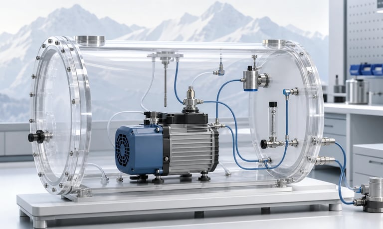
Altitude lowers local atmospheric pressure and gas density, changing the relationship between gauge vacuum and absolute pressure, the mass represented by actual volumetric flow, pump pressure ratio, cooling, sensor readings, outgassing, and the operating point of a complete vacuum system.
How Altitude Affects Vacuum Pump Performance
Vacuum performance changes with altitude because atmospheric pressure and air density decrease as elevation rises. A vacuum reading referenced to local atmosphere therefore means something different at high altitude than at sea level.
The effect depends on how the requirement is written. An application that needs a specific absolute pressure is different from one that needs a fixed gauge vacuum, gas mass flow, standardized flow, chamber exchange rate, suction force, or pressure ratio.
Altitude also changes gas cooling, leakage behavior, sensor output, liquid evaporation, filter pressure loss, and the system operating point. A single universal derating factor cannot describe every pump and installation.
Start with Absolute and Gauge Pressure
Absolute pressure is referenced to a perfect vacuum. Gauge pressure is referenced to local atmospheric pressure.
The relationship is:
Gauge pressure = absolute pressure - local atmospheric pressure
For vacuum expressed as a positive amount below atmosphere:
Vacuum reading = local atmospheric pressure - inlet absolute pressure
At higher altitude, local atmospheric pressure is lower. Even if a pump reaches the same inlet absolute pressure, the numerical vacuum relative to atmosphere is smaller because there is less atmospheric pressure available to remove.
This is why a gauge-vacuum specification can appear worse at altitude while the absolute inlet pressure may remain useful for the process.
Always record local atmospheric pressure and label pump measurements as absolute, gauge, vacuum relative to atmosphere, or differential.
Do Not Treat Percentage Vacuum as Universal
Percentage vacuum is often calculated relative to local atmospheric pressure, but the formula and reference are not always stated.
A percentage based on one atmospheric condition cannot be compared directly with a reading taken at another altitude unless both are converted to absolute pressure using the correct local reference.
Percentage vacuum can also hide the process requirement. Two systems with the same percentage may have different absolute pressures, gas densities, boiling behavior, and mass flow.
For engineering selection, specify:
Inlet absolute pressure
Outlet absolute pressure
Local atmospheric pressure
Required flow basis
Gas and temperature
Gauge or percentage values can still be useful for user interfaces, but the controller should use a defined reference and altitude strategy.
Define What the Process Actually Needs
Different applications respond to altitude in different ways.
Possible requirements include:
A target chamber absolute pressure
A pressure difference for suction or clamping force
Actual volumetric flow through a sampling path
Standardized volumetric flow
Gas mass flow
Air exchange rate in a chamber
Evacuation time from one absolute pressure to another
Maximum leak rate
Differential pressure across a filter or membrane
A vacuum gripper may depend on pressure difference and effective area. An analytical instrument may depend on mass flow. A chamber process may depend on absolute pressure. A sampling system may need a defined actual flow at the local inlet condition.
Write the requirement in physical units with the pressure and temperature reference. Do not use only "vacuum strength" or a catalog gauge value.
Understand Local Atmospheric Pressure
Atmospheric pressure varies with elevation, weather, and local conditions. Altitude is a useful planning input, but measured barometric pressure is the direct reference for a test.
Record:
Installation elevation
Expected atmospheric-pressure range
Weather-related variation where relevant
Operating and storage temperature
Whether the equipment is used in a pressurized cabin or enclosure
A device transported between locations may experience a different ambient pressure even before the pump starts. Sealed chambers, flexible reservoirs, sensor cavities, and packages can develop pressure differences during transport.
Use the expected pressure range rather than one nominal altitude value when the product must operate across multiple locations.
Gauge Vacuum Has a Lower Ceiling at Altitude
The maximum possible difference between local atmosphere and perfect vacuum is the local atmospheric pressure itself. As altitude increases, this available gauge-vacuum range decreases.
For a pump that reaches a given inlet absolute pressure, the gauge vacuum is:
Available gauge vacuum = local atmospheric pressure - inlet absolute pressure
Because the first term becomes smaller at altitude, the gauge value decreases.
This matters for devices specified by suction force, pressure differential, or a gauge switch threshold. A threshold copied from sea-level testing may be unreachable or may represent a different absolute condition at altitude.
Do not respond by selecting only the pump with the largest catalog gauge-vacuum number. Determine the required differential and absolute pressure, then test them at the intended ambient range.
Absolute Vacuum Capability May Change Differently
Ultimate absolute pressure is influenced by diaphragm compression ratio, chamber dead volume, valve leakage, diaphragm stroke, motor speed, gas properties, temperature, and outlet pressure.
At altitude, a pump exhausting to local atmosphere has a lower outlet absolute pressure. This can change compression ratio and valve behavior. The resulting inlet absolute pressure may improve, remain similar, or change in another way depending on the pump design and operating point.
Do not assume that ultimate absolute pressure is constant or that it changes in direct proportion to atmospheric pressure.
Obtain altitude or combined inlet-outlet data for the exact pump where available. Otherwise, test representative units using controlled inlet and outlet absolute pressures.
Remember that ultimate vacuum is a near-zero-flow endpoint. It does not establish the flow available at the required vacuum.
Pressure Ratio Matters
For a pump drawing below atmosphere and exhausting to the surroundings, a simplified pressure ratio is:
Pressure ratio = outlet absolute pressure / inlet absolute pressure
At high altitude, outlet absolute pressure is lower. However, the target inlet pressure may also differ depending on whether the requirement is absolute or gauge.
Two systems with the same pressure difference can have different pressure ratios. Gas compression, temperature, valve flow, leakage, and motor load may therefore differ.
Specify both inlet and outlet absolute pressures. Differential pressure alone is not enough for every diaphragm vacuum-pump comparison.
If the outlet is restricted by a silencer, long tube, valve, or pressurized chamber, measure actual outlet pressure rather than assuming it equals local atmosphere.
Actual Volumetric Flow Changes in Meaning
Actual volumetric flow describes gas volume at the local measurement pressure and temperature. Gas is less dense at lower pressure, so the same actual volume contains less mass at altitude.
A pump may move a similar geometric volume per cycle, yet deliver less gas mass per minute. This matters for ventilation, gas exchange, oxygen transfer, sampling, drying, cooling, and chemical processes.
Do not compare a flow-meter reading at altitude with a sea-level volumetric requirement unless the basis is clear.
Record the pressure and temperature at the flow measurement location. Inlet flow and outlet flow can differ in actual volume because the gas pressure and temperature differ.
For chamber exchange, decide whether the requirement concerns actual chamber volumes per time or a standard quantity of gas.
Standard and Normal Flow Need Defined References
Standardized or normalized volumetric flow converts gas quantity to a stated reference pressure and temperature. This supports mass-flow comparison across different actual conditions.
The terms "standard" and "normal" are not self-defining. Different instruments and industries may use different reference conditions.
Check:
Reference pressure
Reference temperature
Whether humidity is included
Whether flow is based on mass, density, or instrument calibration
Measurement location
A mass-flow sensor may display standard flow while a pump curve reports actual inlet flow. Convert both to a common basis before selecting the pump.
At altitude, a required standard flow may demand a larger actual volumetric flow because each actual liter contains less gas mass.
Pump Curves Must Match the Pressure Basis
Vacuum-pump curves may show flow against gauge vacuum, inlet absolute pressure, or another pressure measure. The test may assume a particular atmospheric pressure.
Before applying a curve, identify:
Pressure reference and units
Local or test atmospheric pressure
Inlet and outlet conditions
Actual or standardized flow
Test gas and humidity
Temperature
Voltage, speed, and driver
Pump orientation and duty
A curve plotted in gauge vacuum at one atmospheric pressure cannot be transferred unchanged to another altitude.
Curves based on inlet absolute pressure are easier to compare across atmospheric conditions, but outlet absolute pressure and gas properties must still be considered.
Ask whether the curve is typical or guaranteed and how production variation is handled.
Filters and Tubing Shift the Operating Point
The pump operates where its curve meets system resistance. Altitude can change gas density and therefore pressure loss in some components, but the result depends on flow regime, geometry, and whether the system controls actual or standardized flow.
Include:
Sampling probe
Inlet filter or membrane
Tubing length and internal diameter
Valves and manifolds
Flow sensor
Moisture separator
Outlet silencer or filter
Exhaust line
If a controller increases actual flow to maintain standard flow at altitude, pressure loss and pump speed may rise.
Measure inlet and outlet pressure close to the pump with clean and realistically loaded components. A remote chamber pressure does not reveal line loss at the pump port.
Do not apply one altitude correction to the pump while leaving the system curve unchanged.
Evacuation Time Can Change
Chamber evacuation time depends on chamber volume, starting and target absolute pressure, gas temperature, leakage, outgassing, conductance, and pump flow across the full pressure range.
At altitude, the chamber starts at a lower absolute ambient pressure if opened to local atmosphere. Reaching a fixed target absolute pressure may involve removing a different gas mass and operating over a different part of the pump curve.
If the requirement is a fixed gauge vacuum, the target absolute pressure also changes with altitude.
Do not estimate evacuation time from free flow alone. Integrate or simulate performance across the pressure curve, then verify with the actual chamber and plumbing.
Leaks and outgassing may dominate near the final pressure. Record stabilization time and pressure rise after pump stop.
Suction Force Depends on Pressure Difference
Vacuum holding, lifting, sealing, or clamping force is related to pressure difference and effective area:
Ideal pressure force = pressure difference × effective area
Actual force is also affected by leakage, surface texture, seal deformation, cup geometry, acceleration, safety factor, and load direction.
Because maximum atmospheric-to-vacuum pressure difference is lower at altitude, the available ideal suction force can decrease even if the pump reaches a low absolute pressure.
Test the actual gripper, seal, or fixture at the highest installation altitude, worst leakage surface, load orientation, acceleration, and wear condition.
Do not use theoretical force as a rated safe load without mechanical and system validation.
Cooling Becomes More Difficult
Lower air density can reduce convective cooling of the motor, driver, pump head, and enclosure. Fans may also move less gas mass for the same actual volume.
Temperature can rise even if electrical input is unchanged. A controller that increases pump speed to maintain flow may add further heat.
Measure:
Motor, driver, pump-head, and enclosure temperature
Inlet and outlet gas temperature
Supply voltage and current
Pump speed
Flow and pressure
Time to thermal steady state
Test in the final enclosure at representative altitude or in a controlled low-pressure environment where required.
Thermal derating cannot be assumed from altitude alone. Enclosure design, airflow, pump duty, electronics, and ambient temperature determine the result.
Motors and Electronics Also Need Altitude Review
The pump is part of an electrical system. Altitude can affect cooling and, at sufficiently reduced pressure, electrical insulation and spacing requirements depending on voltage and product standards.
Review:
Motor and driver temperature
Current limit and startup
Power-supply capability
Connector and wiring environment
Applicable insulation and clearance requirements
Sensor venting and reference pressure
Fan and heat-sink performance
Use the applicable product safety and compliance process for the final equipment. General pump altitude data do not replace product-level electrical assessment.
If a pressure sensor has a vented gauge reference, confirm that its vent tracks ambient pressure without blockage or condensation. A sealed-gauge or absolute sensor behaves differently.
Sensors Can Create Apparent Performance Changes
Gauge sensors reference ambient pressure directly or through a vent. Absolute sensors reference an internal vacuum. Differential sensors compare two ports.
At altitude, a gauge sensor may display a different numerical vacuum for the same absolute inlet pressure. A control algorithm using that value may change pump command or trigger an alarm unexpectedly.
Check:
Sensor pressure type
Range and accuracy
Barometric compensation
Vent routing and contamination
Temperature compensation
Units and sign convention
Calibration pressure
Software conversion and thresholds
Use an independent barometer or absolute reference during validation.
Avoid calibrating a gauge-vacuum threshold at one altitude and assuming it represents the same process state everywhere.
Outgassing, Boiling, and Condensation May Change
Lower pressure can cause dissolved gases to leave liquids and can increase evaporation. If a gas-sampling or vacuum system contains moisture, solvent, oil, adhesive, plastic, or product residue, outgassing may increase the gas load.
Possible consequences include:
Longer evacuation time
Bubbles or foam
Vapor entering the pump
Valve contamination
Condensation downstream
Changed sample composition
Cooling from evaporation
The relevant limit depends on fluid vapor pressure and temperature. A vacuum pump cannot reduce total pressure below the vapor contribution of materials present without continued vapor removal and appropriate system design.
Review all liquids and volatile materials in the chamber and plumbing. Use separators, traps, controlled temperature, ventilation, or compatible materials where justified.
Do not assume a dry-gas pump can handle condensed liquid.
Leakage and Permeation Become More Important
Vacuum-system performance depends on pump capacity minus gas entering through leaks, permeation, outgassing, valves, and process flow.
At altitude, the pressure differences across some seals change, while the target absolute pressure and gas density may also change. The relative contribution of a fixed leak can become more important near the target pressure.
Test:
Pressure decay or rise after pump stop
Fittings and tube connections
Valve leakage
Chamber seals
Flexible tubing permeation
Sensor and service ports
Production assembly variation
Use a leak method appropriate to the system and gas. A component that does not leak outward under positive pressure may still admit air under vacuum.
Separate pump ultimate capability from the final pressure of a leaking or outgassing system.
Avoid Simple Universal Altitude Corrections
It is tempting to multiply flow or vacuum by one altitude factor. This can fail because different outputs scale differently.
Altitude affects:
Atmospheric reference
Gas density
Gauge vacuum
Absolute inlet and outlet pressure
Pressure ratio
Actual and standardized flow
System pressure loss
Motor and driver cooling
Leakage and outgassing
Sensor interpretation
The pump curve, system curve, and control strategy interact. Use condition-specific calculations and tests.
If a supplier provides validated correction factors for the exact pump and performance measure, follow their definitions and range. Do not transfer a factor from another pump architecture or measurement basis.
Build an Altitude Validation Test
Test at the intended minimum and maximum atmospheric pressure using the final pump, fluid path, chamber, filters, sensors, electronics, control software, and enclosure.
Record:
Local atmospheric pressure
Installation-equivalent altitude
Inlet and outlet absolute pressure
Gauge or differential readings
Actual, standardized, or mass-flow basis
Gas identity, humidity, and temperature
Pump speed, voltage, and current
Motor, driver, and enclosure temperature
Evacuation time and final pressure
Leakage or pressure rise after stop
Include clean and loaded filters, minimum and maximum ambient temperature, supply-voltage limits, startup, continuous operation, and fault conditions.
Use multiple pump and sensor samples. Verify that software thresholds, displayed units, alarms, and stored calibration remain correct across locations.
Altitude Performance Checklist
Process requirement defined as absolute pressure, differential, flow, force, or evacuation time
Local atmospheric-pressure range identified
Gauge, absolute, vacuum, and differential values labeled correctly
Percentage-vacuum reference and formula verified
Required inlet and outlet absolute pressures defined
Actual, standardized, normal, and mass-flow bases distinguished
Pump curve test atmosphere, gas, temperature, voltage, and duty confirmed
System restrictions and loaded filters included
Evacuation time evaluated across the full pressure curve
Suction-force requirement checked at maximum altitude
Cooling and thermal steady state tested
Motor, driver, power supply, and sensor altitude behavior reviewed
Sensor reference, venting, thresholds, and barometric compensation verified
Outgassing, evaporation, condensation, and liquid carryover considered
Leakage and permeation measured in the complete system
Supplier correction factors used only within their defined range
Production pump and sensor variation included
Final enclosure and control software validated at pressure extremes
Common Altitude Mistakes
Comparing gauge vacuum without local atmospheric pressure
Treating percentage vacuum as an absolute measure
Assuming the same gauge threshold represents the same process state
Using free flow to predict evacuation time
Treating actual volumetric flow as constant gas mass flow
Mixing actual and standardized flow values
Correcting the pump but not the system resistance
Assuming ultimate absolute pressure is unchanged at every altitude
Ignoring lower suction-force potential
Ignoring reduced motor and driver cooling
Using a vented gauge sensor with a blocked reference port
Forgetting outgassing and vapor load
Applying one universal altitude derating percentage
Testing the pump without the final chamber, filters, and enclosure
Frequently Asked Questions
Does a vacuum pump create less vacuum at high altitude?
Its gauge-vacuum reading usually has a lower available range because local atmospheric pressure is lower. Absolute pressure capability may change differently and must be checked for the exact pump and conditions.
Why does the same actual airflow contain less gas at altitude?
Gas density is lower at reduced pressure, so the same actual volume contains less mass. Standardized flow corrects volume to a defined reference condition.
Can I use one altitude correction factor for pump flow?
Not reliably. Actual flow, standard flow, gauge vacuum, absolute pressure, pressure loss, cooling, and control response do not all scale by one factor.
Does altitude reduce vacuum holding force?
It can. The maximum pressure difference between local atmosphere and vacuum is lower at altitude, so available ideal suction force decreases for the same effective area.
Should vacuum controls use absolute or gauge sensors?
It depends on the process. Absolute sensing is useful for an absolute-pressure requirement, while differential or gauge sensing may suit pressure-force control. Define altitude behavior and thresholds explicitly.
How should an OEM test a vacuum pump for altitude?
Test the complete system across the expected atmospheric-pressure range while recording absolute inlet and outlet pressure, flow basis, gas, temperature, voltage, current, speed, heat, leakage, and control response.
Kamoer Altitude and Vacuum Pump Support
Kamoer can help interpret absolute and gauge pressure, flow basis, altitude, inlet and outlet loading, gas conditions, thermal behavior, sensors, and representative OEM tests for diaphragm vacuum-pump systems.
Related Stories
Kamoer Fluid Tech (Shanghai) Co., Ltd.
pump@kamoer.com