

Diaphragm Gas Pumps for Vacuum and Pressure Applications
APPLICATIONSLABORATORY AUTOMATION
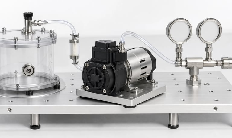
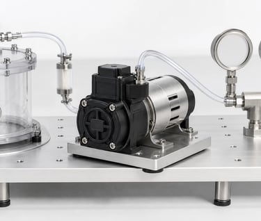
Reliable vacuum and pressure systems depend on diaphragm gas pumps matched to the real flow and pressure operating point, gas composition, wetted materials, leakage, control, power, noise, thermal limits, and duty cycle.
Diaphragm Gas Pumps for Vacuum and Pressure Applications
Diaphragm gas pumps are used in gas sampling, sensor aspiration, pneumatic control, vacuum generation, pressure supply, air transfer, and analytical equipment. Their compact size and dry pumping mechanism can make them useful in OEM systems, but selection requires more than comparing maximum flow, maximum vacuum, and maximum pressure.
The pump must deliver the required flow at the system's actual inlet vacuum or outlet pressure. Gas composition, leakage, moisture, altitude, duty cycle, control method, noise, and thermal conditions also affect suitability.
How a Diaphragm Gas Pump Works
An electric motor drives an eccentric mechanism that flexes a diaphragm. As chamber volume increases, the inlet valve opens and gas enters. As volume decreases, the inlet closes, the outlet valve opens, and gas is discharged.
The diaphragm separates the gas chamber from much of the drive mechanism. However, the sample still contacts the diaphragm, valves, chamber, ports, and connected fluid path. These wetted materials must be evaluated for the actual gas.
Reciprocating motion also creates periodic flow and pressure variation. Valve response, pump speed, chamber design, and downstream volume determine how much pulsation reaches the system.
Vacuum and Pressure Describe Different Conditions
In vacuum service, the pump draws gas from a component or chamber and exhausts it downstream. The inlet operates below ambient pressure. In pressure service, the pump draws from a source and discharges against resistance above ambient pressure.
Some systems use both sides simultaneously—for example, drawing gas through a sensor and exhausting through a filter or long tube. In that case, inlet vacuum and outlet pressure both contribute to pump load.
Maximum vacuum is normally measured near zero inlet flow. Maximum pressure is normally measured near zero outlet flow. Neither value is the normal flow capacity at that condition. Likewise, maximum free flow is measured with little restriction and cannot be assumed at maximum vacuum or pressure.
Define the Real Operating Point
Specify the pump requirement as a combination:
Required gas flow
Inlet absolute pressure or vacuum relative to ambient
Outlet absolute pressure or gauge pressure
Gas and ambient temperature
Local atmospheric pressure or altitude
Supply voltage and control mode
For a vacuum application, calculate or measure the resistance upstream of the pump. For a pressure application, evaluate downstream resistance. When both sides are restricted, include both.
Plot the required condition against the manufacturer's relevant performance curve. Leave appropriate margin for tolerances, aging, filter loading, voltage variation, temperature, and environmental conditions without selecting so much excess capacity that control, power, heat, or noise becomes difficult.
Read Pump Curves Carefully
A performance curve typically shows flow changing as vacuum or pressure increases. Confirm:
Whether the horizontal axis uses gauge or absolute pressure
Whether vacuum is shown as negative gauge pressure, absolute pressure, or a percentage
Which gas and temperature were used
Supply voltage and motor speed
Whether the data represents a typical unit or guaranteed limits
Whether inlet and outlet restrictions were applied separately
Whether flow is volumetric or standardized
Do not combine the maximum values from separate specifications as though they occur simultaneously. If the required point is not shown, request representative test data or evaluate a sample in the final circuit.
Understand Flow Reference Conditions
Gas volume changes with absolute pressure and temperature. A volumetric flow measured at the pump inlet can differ from the volume measured at the outlet. Standardized flow converts the gas quantity to defined reference conditions.
When comparing specifications, identify where and how flow is measured. For processes sensitive to gas quantity rather than local volume, mass-flow measurement or appropriate pressure and temperature compensation may be needed.
Altitude reduces atmospheric pressure and changes gas density. A pump may show different volumetric flow, mass delivery, vacuum behavior, temperature, and calibration at elevation.
Calculate System Resistance
Tubing, filters, valves, mufflers, orifices, sensor cells, manifolds, fittings, and exhaust paths create pressure loss. Resistance often rises as flow increases and can change during use.
Common changes include:
Dust loading in a filter
Condensate in a trap or tube
A valve that is partially closed
A kinked or aging hose
A different probe or accessory
Altitude or process-pressure variation
Measure flow, inlet vacuum, outlet pressure, current, and pump temperature in the assembled system. Test both clean and expected end-of-service conditions.
Evaluate Gas and Material Compatibility
Provide gas composition, concentration, humidity, temperature, pressure, and exposure time. Include calibration gases, cleaning gases, vapors, aerosols, and foreseeable contaminants.
Evaluate the diaphragm, valves, chamber, seals, ports, tubing, fittings, filters, and any adhesive in contact with the gas. Consider swelling, hardening, corrosion, permeation, adsorption, outgassing, and chemical reaction.
For trace analysis, a chemically resistant material may still adsorb the target compound or release an interferent. Validate the complete path using the intended measurement method.
Where flammable, toxic, oxidizing, or otherwise hazardous gases are present, use only components documented for the specific installation and applicable requirements. System-level ventilation, containment, ignition control, and risk assessment remain necessary.
Manage Moisture and Liquid Ingress
Diaphragm gas pumps are designed primarily to move gas. Humid gas may condense in cooler tubing or inside the system, and droplets can block flow, damage sensors, contaminate valves, or change pump performance.
Possible controls include heated lines, insulation, water traps, hydrophobic filters, dryers, drainage, and moisture detection. Each adds resistance and may affect the target gas.
Do not assume a pump can ingest liquid because it handles humid air. Confirm the specific model's permitted conditions and validate foreseeable condensation, orientation, restart, and fault scenarios.
Control Pulsation, Noise, and Vibration
Diaphragm motion produces pulsating flow. This can disturb pressure sensors, flow sensors, sensitive analytical cells, or pneumatic actuators.
Possible measures include a suitable pump speed, compliant tubing, a compatible damper, accumulator volume, restriction, or closed-loop control. Added volume can slow system response and increase carryover, so validate the complete system.
Pump noise includes airborne sound and structure-borne vibration. Test inside the final enclosure. Resilient mounts, flexible connections, adequate clearance, and suitable speed control can reduce transmission, but mounting must remain secure during shock and transport.
Choose the Motor and Control Method
Brushed DC motors can offer straightforward, economical control, while brushless motors may be considered when longer service, lower electrical noise, speed feedback, or different control features are required. Actual life and performance depend on model, load, environment, and duty cycle.
Control options may include fixed voltage, PWM, analog commands, or digital communication. Confirm the method supported by the specific pump electronics.
Useful strategies include fast evacuation followed by lower holding speed, variable flow, soft start, pressure regulation, and fault detection from speed, current, flow, or pressure feedback.
Check Power, Heat, and Duty Cycle
Motor current often changes with the pressure condition. A blocked line may produce low flow while increasing load and temperature. Measure startup current and steady-state current at the real operating point.
Define continuous, intermittent, and peak operation, including on-time, off-time, starts per hour, ambient temperature, enclosure ventilation, and neighboring heat sources.
Test the pump inside the final product until temperatures stabilize. Do not assume a pump suitable for brief operation can run continuously, or that an open-bench test represents a sealed enclosure.
Consider Series and Parallel Configurations
Multiple pump stages or pumps may sometimes extend vacuum, pressure, or flow capability. Series arrangements can alter achievable pressure ratio, while parallel arrangements can increase flow under some conditions.
Results are not obtained by simply adding catalog maximums. Valve behavior, leakage, unequal flow, shared restrictions, motor tolerances, and thermal load affect performance. Use manufacturer guidance and validate the actual configuration.
Plan Fault Detection and Maintenance
Monitor variables that help distinguish faults:
Flow
Inlet vacuum and outlet pressure
Motor current or speed
Pump and enclosure temperature
Filter runtime
Moisture or liquid detection
Fault logic may identify an open tube, leak, blocked filter, closed valve, liquid ingress, worn diaphragm, failed valve, stalled motor, or sensor error.
Make filters, traps, tubing, and pump modules accessible. Verify flow, pressure, and leakage after service. Establish service intervals from representative testing rather than assuming a universal diaphragm, valve, or motor life.
Validation Checklist
Required flow at the actual inlet vacuum and outlet pressure
Minimum and maximum supply voltage
Gas composition, humidity, and temperature
Clean and loaded filters
Full tubing, valve, sensor, muffler, and exhaust path
Sea-level and intended altitude conditions
Leakage, adsorption, permeation, and outgassing
Pulsation at sensitive components
Noise and vibration in the final enclosure
Startup, steady operation, speed changes, and shutdown
Continuous, intermittent, and peak duty cycles
Thermal stabilization at worst restriction
Blockage, leak, condensation, and power-loss faults
Performance with new and aged critical components
Common Selection Mistakes
Treating maximum flow, vacuum, and pressure as one operating point
Confusing gauge pressure with absolute pressure
Comparing flows measured at different reference conditions
Ignoring restriction on the opposite side of the pump
Selecting from clean-filter performance only
Testing at room temperature and sea level only
Assuming chemical resistance proves sample integrity
Allowing condensate to reach a pump without validation
Evaluating noise outside the final enclosure
Omitting thermal and life testing at the real load
Frequently Asked Questions
Can one diaphragm gas pump provide both vacuum and pressure?
Many pumps create suction at the inlet and pressure at the outlet simultaneously. Available flow depends on the combined inlet and outlet conditions, so validate the required operating point.
Does maximum vacuum mean the pump still provides full flow?
No. Maximum vacuum is generally approached as inlet flow becomes very low. Use the pump curve to find flow at the required vacuum.
What is the difference between gauge and absolute pressure?
Gauge pressure is referenced to local atmospheric pressure. Absolute pressure is referenced to a perfect vacuum. Confirm which unit and reference a specification uses.
Can a diaphragm gas pump run continuously?
Only if the specific model is rated and validated for the required operating point, voltage, ambient temperature, enclosure, and duty cycle.
Why does pump flow decrease after installation?
Filters, tubing, valves, sensors, exhaust restrictions, leaks, voltage drop, and altitude can move the pump away from its free-flow condition.
Kamoer Diaphragm Gas Pump Support
Kamoer can help evaluate flow, vacuum, pressure, gas compatibility, wetted materials, leakage, moisture, control, noise, power, thermal conditions, duty cycle, and OEM integration for diaphragm gas pump applications.
Related Stories
Kamoer Fluid Tech (Shanghai) Co., Ltd.
pump@kamoer.com