

Brushless vs Brushed DC Motors for Micro Pumps
PUMP SELECTION GUIDES
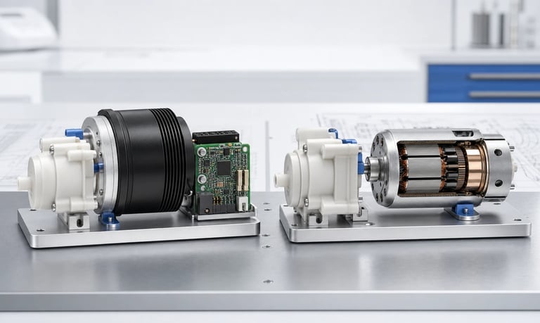
Brushless and brushed DC motors can both drive micro pumps, but they differ in commutation, wear mechanisms, driver requirements, speed control, electrical noise, acoustic behavior, thermal performance, cost, size, and suitability for the application's duty cycle and service expectations.
Brushless vs Brushed DC Motors for Micro Pumps
The motor affects much more than pump speed. It influences control architecture, heat, acoustic behavior, electromagnetic compatibility, startup, service expectations, cost, size, and the amount of electronics an OEM must integrate.
Brushed DC motors use mechanical brushes and a commutator to switch current in the rotating armature. Brushless DC motors use electronic commutation and a permanent-magnet rotor. Brushless designs remove brush wear, but they add driver electronics and control decisions. Brushed designs can be electrically simple, but brush and commutator behavior changes over time.
Neither type is automatically best for every micro pump. Selection should be based on the complete pump, gearbox, driver, fluid load, operating profile, environment, and product requirements.
Start with the Pump Requirement
Select the motor only after defining what the pump must do. The same motor can behave differently when driving a peristaltic head, diaphragm mechanism, gear train, or another load.
Document:
Minimum, typical, and maximum flow or dose
Required pump speed and speed range
Startup torque and peak load
Inlet vacuum and outlet pressure
Continuous, intermittent, or short-burst duty
Starts, stops, reversals, and braking
Minimum and maximum supply voltage
Ambient and enclosure temperature
Noise and vibration limits
Control accuracy and feedback needs
Expected operating exposure and service strategy
Size, weight, power, and cost targets
Motor torque margin should include cold fluid, high viscosity, aged peristaltic tubing, maximum pressure, minimum supply voltage, and production variation.
Do not choose a motor from free-running speed alone. Pump load, driver behavior, gearbox losses, and temperature determine the usable operating point.
How Brushed DC Motors Work
A brushed DC motor uses carbon or metal brushes that contact segmented commutator surfaces. As the rotor turns, this mechanical interface switches current between armature windings.
Basic speed control can be straightforward. Applying DC voltage or pulse-width modulation through a suitable switch can control average motor input. Reversing polarity can reverse direction when the motor, pump, driver, and fluid path permit it.
Advantages may include:
Simple external drive architecture
Low initial component cost in many small sizes
Direct response to applied voltage
Compact availability across many pump designs
Familiar control and sourcing options
Limitations may include:
Brush and commutator wear
Electrical arcing and conducted or radiated noise
Torque and speed ripple
Acoustic change during life
Debris from brush wear
Greater sensitivity to frequent starts, stalls, and high current
The importance of each factor depends on the exact motor construction and operating profile. A high-quality brushed motor operated conservatively may outperform a poorly matched brushless system in a specific application.
How Brushless DC Motors Work
A brushless DC motor uses electronic switches to energize stator windings according to rotor position. Position information may come from Hall sensors, an encoder, back-electromotive-force detection, or another commutation method.
The driver may be built into the pump or provided by the OEM. Interfaces can range from simple power and speed-command wires to digital communication with speed, current, temperature, and fault reporting.
Advantages may include:
No brush or commutator wear mechanism
Stable electronic commutation
Potentially longer operating exposure
Potentially higher efficiency and lower motor heat
Better support for closed-loop speed control
Reduced brush arcing and brush debris
Limitations may include:
Additional driver electronics
More complex startup and low-speed control
Switching-related electromagnetic and acoustic noise
Sensitivity to driver tuning and firmware
Higher component or integration cost in some designs
Electronic failure modes and thermal limits
Brushless does not mean maintenance-free or unlimited life. Bearings, gears, pump tubing, diaphragms, valves, seals, solder joints, connectors, magnets, and driver components still age.
Compare Wear and Service Life
In a brushed motor, the brush-commutator interface is a primary wear mechanism. Wear depends on current, speed, duty cycle, start-stop frequency, direction changes, stalls, temperature, humidity, vibration, brush material, commutator construction, and manufacturing variation.
As the interface changes, the motor may show:
Increased electrical noise
Unstable contact at certain rotor positions
Rising or irregular current
Changed acoustic tone
Reduced torque or failed startup
Brush debris
Brushless motors eliminate this interface, so they are often considered for longer duty or high-cycle products. Their system life may instead be limited by bearings, electronics, winding insulation, magnets, gearbox, or the pump mechanism.
Do not compare motors using one generic lifetime number. Request test conditions and validate the complete pump under representative speed, torque, temperature, voltage, start-stop, pressure, and fluid conditions.
If a peristaltic tube or diaphragm requires replacement much earlier than either motor, motor life may not be the only service driver. Evaluate how the entire module will be maintained.
Evaluate Continuous and Intermittent Duty
Continuous operation emphasizes efficiency, steady-state heat, bearing performance, lubrication, driver temperature, and pump-component life.
Intermittent operation emphasizes startup, acceleration, peak current, thermal cycling, brush arcing, commutation reliability, and the number of cycles. A low overall run time can still be demanding if the motor starts and stops very frequently.
Record the actual profile:
Run duration
Idle duration
Starts per operating period
Acceleration and deceleration
Normal and peak torque
Reversals
Stall or blockage response
Enclosure temperature over repeated cycles
Do not convert intermittent use into average power alone. Short high-current events can stress brushes, commutator surfaces, driver switches, gears, connectors, and the power supply.
Test the longest continuous run and the most demanding repeated cycle separately.
Compare Speed Control
Brushed motor speed is influenced by applied voltage, load torque, winding resistance, brush voltage drop, temperature, and motor characteristics. Open-loop PWM can provide useful control, but a fixed duty command does not guarantee fixed speed or flow.
Brushless systems can regulate commutation and often support closed-loop speed. Whether they actually hold speed depends on the driver, feedback method, resolution, tuning, torque margin, supply voltage, and operating range.
For either motor type, define:
Minimum reliable start speed
Minimum stable running speed
Maximum required speed
Speed accuracy and repeatability
Response to pressure and fluid changes
Direction-control behavior
Acceleration and stopping requirements
Feedback signal and fault handling
Peristaltic roller loading and diaphragm strokes create cyclic torque. An aggressively tuned controller may chase this natural load variation and add speed modulation, noise, or current ripple.
Measure actual shaft or pump speed where possible. Do not infer precise speed only from PWM duty or supply voltage.
Consider Low-Speed Operation
Low-speed pumping is important for small doses and low flow. Both motor types can have practical limitations.
A brushed motor may experience stick-slip, insufficient starting torque, brush-contact variation, or large speed change with load at very low input. A geared motor can improve usable torque and resolution but adds backlash, noise, size, and losses.
A brushless motor may require enough speed to generate a usable sensorless commutation signal. Hall-sensored or encoder-based systems can support lower-speed control, but performance depends on pole count, feedback resolution, driver algorithm, and load.
Stepper-based pumps may be considered when discrete position control is more important than motor efficiency or continuous rotation, but they introduce a different set of torque, resonance, heat, and control tradeoffs.
Test the complete pump at its minimum required flow with maximum pressure, cold or viscous fluid, minimum supply voltage, and aged consumables.
Compare Efficiency and Heat
Brushless motors can achieve lower commutation loss and higher efficiency in a well-designed operating range, but system efficiency includes the driver, gearbox, pump mechanism, and fluid load.
Brushed motors add brush contact loss and armature heating. At high load or low speed, current may increase and cooling may be reduced. Brushless drivers also generate switching and conduction losses, especially when integrated into a small enclosure.
Measure:
Supply voltage and current
Electrical input power
Pump speed, flow, and pressure
Motor, driver, gearbox, and pump-head temperature
Enclosure-air and fluid temperature
Warm-up time and thermal steady state
Do not compare motors only at no load. A more efficient motor can still run hotter if it is smaller, poorly cooled, operated away from its efficient range, or paired with a less efficient gearbox.
Thermal design also affects tubing, valves, seals, fluid viscosity, electronics, and calibration. Verify the final closed enclosure.
Compare Acoustic Noise and Vibration
Brushed motors can create brush contact noise, commutator tones, torque ripple, and changing sound as the interface wears. Brushless motors remove brush contact but can produce commutation tones, PWM-related sound, cogging effects, and driver-controlled speed modulation.
The pump mechanism and gearbox may dominate both motor types. Peristaltic roller passage, diaphragm valves, pressure pulsation, and mounting resonance can be louder than the motor.
Compare candidates in the final mechanical structure at the same delivered flow and pressure. Record:
Overall sound and frequency spectrum
Mount and panel vibration
Speed and operating point
Startup, steady operation, and shutdown
Cold and warm condition
New and aged pump samples
Changing PWM or commutation frequency may move an audible tone, but it can affect torque, driver heat, electromagnetic compatibility, and control stability. Use settings approved for the motor and driver.
Compare Electromagnetic Interference
Mechanical brushes interrupt current and can create broadband electrical noise and arcing. This may couple through power lines, wiring, nearby sensors, radio circuits, or measurement electronics.
Brushless drivers switch phase current electronically. Their interference is often more predictable in frequency but can still be significant because of fast voltage and current transitions.
For either type, review:
Power-supply impedance and filtering
Current-loop area
Cable length and routing
Ground and return-current paths
Shielding and enclosure construction
Connector contact and motor suppression components
Driver switching edges and frequency
Proximity to sensitive analog, optical, radio, or measurement circuits
Component-level emissions data does not prove the finished OEM product will pass its applicable electromagnetic requirements. Test the complete product in its production configuration.
Do not add capacitors, inductors, or suppression networks without checking driver stability, motor voltage, heat, start performance, and safety requirements.
Evaluate Electronics and Integration Complexity
A brushed motor may need only a switch or H-bridge, current measurement, protection, and optional speed feedback. Simplicity can reduce software and component count, but the OEM still needs fault handling and supply protection.
A brushless motor may use:
An integrated driver inside the pump
An external commutation controller
Hall or encoder inputs
Analog, PWM, frequency, or digital speed command
Speed, current, temperature, or fault outputs
Firmware configuration and communication protocol
An integrated driver can simplify OEM hardware but creates interface and supply requirements. An external driver provides control flexibility but adds development, thermal, electromagnetic, and validation work.
Ask what happens during power-up, brownout, stalled rotor, missing sensor, communication loss, overtemperature, reversed connection, and fault recovery. Confirm that the pump cannot start unexpectedly.
Control-interface availability may matter more than the motor label. Compare the complete pump-and-driver solution.
Check Startup, Stall, and Fault Behavior
Pumps can require their highest torque at cold startup, with viscous fluid, aged tubing, residual pressure, or a sticky valve. Verify minimum supply voltage and the most demanding fluid condition.
For brushed systems, high start or stall current can accelerate brush and commutator stress, heat windings, and load the driver. For brushless systems, startup depends on rotor-position detection, commutation logic, current limit, and the ability to overcome static load.
Test:
Normal and worst-case startup
Restart against residual pressure
Cold and high-viscosity fluid
Maximum approved tube occlusion
Blocked inlet and outlet
Locked rotor
Minimum and maximum voltage
Communication interruption
Sensor or feedback failure
Repeated fault and reset
Define detection time, current and temperature limits, shutdown response, user indication, and recovery behavior. A controller that repeatedly retries a mechanical blockage may create more heat or an unintended dose after the obstruction clears.
Consider Direction Reversal and Braking
Some applications reverse the pump for priming, purging, suck-back, or bidirectional transfer. Motor reversibility does not guarantee that the pump mechanism, valves, tubing, and process are equally effective in both directions.
Brushed motors can reverse by polarity through a suitable driver. Brushless reversal must be supported by the controller and commutation method. Both require controlled deceleration and current handling.
Review:
Required stop time before reversal
Regenerative or braking current
Gearbox backlash
Tube and roller loading
Diaphragm check-valve direction
Fluid cross-contamination or air entry
Calibration in each direction
Post-stop dripping and pressure release
Frequent reversals may increase gear, bearing, coupling, brush, or drive stress. Include the actual reversal cycle in life testing.
Review Environmental Conditions
Temperature, humidity, altitude, dust, chemical vapor, condensation, shock, and vibration can influence both motor types.
Brush commutation can be sensitive to environment and contamination. Brushless electronics introduce circuit boards, sensors, solder joints, and switching devices that must also tolerate the product environment.
Check:
Operating and storage temperature
Condensation and humidity
Dust and brush-debris containment
Chemical vapor near the motor and driver
Heat from nearby components
Reduced cooling in sealed enclosures
Mechanical shock and transport vibration
Required ingress protection at the product level
If the application has a potentially flammable atmosphere, oxygen-enriched area, or another special hazard, do not select a motor from general brush or brushless guidance. Use the applicable safety assessment and approved equipment requirements.
Compare Cost at the System Level
Motor purchase price is only one part of cost. Include:
Driver electronics and protection
Speed or position sensors
Connectors and wiring
Filtering and electromagnetic mitigation
Thermal management
Firmware development and validation
Acoustic isolation
Calibration and end-of-line testing
Expected service and warranty exposure
Supply continuity and change control
A lower-cost brushed motor may be the right choice for low-use equipment with simple control. A brushless solution may reduce maintenance or provide control features that justify higher initial cost in continuous or high-cycle service.
The result depends on operating profile and product economics. Do not use a universal break-even point.
Validate Production Variation and Supplier Changes
Motor resistance, magnet strength, brush seating, bearing friction, gearbox efficiency, Hall alignment, driver components, and assembly tolerances can change performance between units.
Test multiple production-representative samples across:
Minimum and maximum supply voltage
Speed and torque range
Pressure and fluid extremes
Cold startup and thermal steady state
Acoustic and vibration limits
Current and driver temperature
Stall and protection behavior
Life and start-stop exposure
Define critical part numbers, revisions, approved suppliers, firmware, driver configuration, and change-notification requirements.
A second-source motor with similar dimensions and voltage is not automatically equivalent. Revalidate flow, torque margin, heat, noise, electromagnetic behavior, life mechanisms, and control response.
Selection Checklist
Required pump speed, flow, pressure, torque, and direction defined
Continuous and intermittent operating profiles documented
Starts, stops, reversals, and stall exposure included
Minimum and maximum supply voltage identified
Low-speed startup and stable running verified
Speed accuracy and feedback requirements defined
Motor, driver, gearbox, and pump heat measured in the enclosure
Noise and vibration compared at equal pump output
Conducted and radiated interference evaluated in the product
Driver interface, startup state, and communication behavior verified
Fault detection, shutdown, retry, and recovery tested
Environmental and storage conditions included
Pump consumable life considered with motor life
System-level cost includes electronics, firmware, EMC, thermal, and service
Multiple production samples and aged units evaluated
Supplier revisions and alternate sources controlled
Common Motor-Selection Mistakes
Assuming brushless is automatically quieter
Comparing no-load motor data instead of pump output under pressure
Treating brushless as unlimited-life technology
Using average duty cycle without counting starts and stalls
Selecting from rated voltage without checking minimum-voltage startup
Assuming PWM duty equals motor speed
Ignoring driver and gearbox heat
Comparing purchase price without electronics and validation cost
Changing PWM frequency without checking torque, heat, and EMC
Testing one speed while the product uses a wide range
Ignoring peristaltic tube or diaphragm life when comparing motor life
Treating similar motor dimensions as proof of second-source equivalence
Evaluating the motor outside the final enclosure
Omitting fault-retry and unexpected-start behavior
Frequently Asked Questions
Are brushless micro pumps always better than brushed pumps?
No. Brushless pumps can offer useful life and control advantages, while brushed pumps may provide simpler electronics and lower cost. The correct choice depends on duty, load, environment, control, noise, and product economics.
Do brushless pump motors last longer?
They eliminate brush and commutator wear, which can support longer operating exposure. Overall pump life may still be limited by bearings, gears, tubing, diaphragms, valves, electronics, or the application load.
Which motor type is quieter?
Either can be quieter in a particular system. Brushed motors have brush and commutator noise; brushless motors can have commutation, PWM, cogging, and driver-related tones. The pump mechanism and enclosure often dominate.
Which motor is better for continuous operation?
Brushless motors are often considered for continuous or high-cycle use because they remove brush wear and may improve efficiency. Final selection still requires thermal, load, pump-life, and driver validation.
Can a brushed motor provide accurate dosing?
Yes, when the pump, control, feedback, calibration, pressure, tubing, and fluid conditions support the required accuracy. Open-loop voltage or PWM alone does not guarantee fixed flow.
What information should an OEM provide when selecting a pump motor?
Provide flow, pressure, speed range, fluid, temperature, supply voltage, duty cycle, starts, reversals, noise limits, control interface, enclosure conditions, service target, and fault requirements.
Kamoer Pump Motor Selection Support
Kamoer can help compare brushed and brushless pump configurations using required flow, pressure, duty cycle, speed control, motor load, heat, noise, driver interface, fault behavior, and representative OEM testing conditions.
Related Stories
Kamoer Fluid Tech (Shanghai) Co., Ltd.
pump@kamoer.com